8.Following installation, the
.
Figure 8. Back-UPS HS IP Address and MAC Address Screen
9.If there are no DHCP services on the network, or if you want to assign an IP Address you can easily remember, you can manually assign an IP Address to the
To assign an IP Address to your computer, please read and follow the directions that came with your computer.
Figure 9. Assign IP Address Screen
Figure 10. Blank Assign IP Address Screen
10.You can assign a name to the
Figure 11. Assign Name Screen
11.To reset the
 Manual Reset
Access
Figure 12. Manual Reset Access
12.Before performing any UPS maintenance task, check the Status of the UPS by clicking on the Status link. The screen shown in Figure 13 will be displayed.
Figure 13. Back-UPS HS 500 Status Screen
13.To change the configuration of the
When this page is displayed, enter a default Username of apc, and a default Password of apc. To change the Username or Password, you must log on and then click Maintenance (Figure 14).
Note: You can also access the Logon Page Screen by entering the IP Address into the Address line of your browser.
Figure 14. Log On Screen
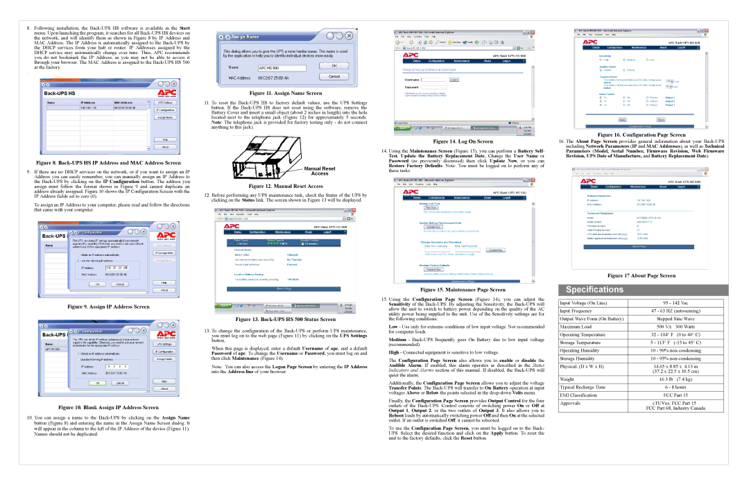
14.Using the Maintenance Screen (Figure 15), you can perform a Battery Self- Test, Update the Battery Replacement Date, Change the User Name or Password (as previously discussed) then click Update Now, or you can Restore Factory Defaults. Note: You must be logged on to perform any of these tasks.
Figure 15. Maintenance Page Screen
15.Using the Configuration Page Screen (Figure 14), you can adjust the Sensitivity of the
Low - Use only for extreme conditions of low input voltage. Not recommended for computer loads.
Medium -
High - Connected equipment is sensitive to low voltage.
The Configuration Page Screen also allows you to enable or disable the Audible Alarm. If enabled, this alarm operates as described in the Status Indicators and Alarms section of this manual. If disabled, the
Additionally, the Configuration Page Screen allows you to adjust the voltage Transfer Points. The
Finally, the Configuration Page Screen provides Output Control for the four outlets of the
To use the Configuration Page Screen, you must be logged on to the Back- UPS. Select the desired function and click on the Apply button. To reset the unit to the factory defaults, click the Reset button.
Figure 16. Configuration Page Screen
16.The About Page Screen provides general information about your
Figure 17 About Page Screen
Specifications
Input Voltage (On Line) | 95 - 142 Vac | |
Input Frequency | 47 - 63 HZ (autosensing) | |
|
| |
Output Wave Form (On Battery) | Stepped Sine Wave | |
|
|
|
Maximum Load | 500 VA | 300 Watts |
|
|
|
Operating Temperature | 32 - 104° F | (0 to 40° C) |
|
| |
Storage Temperature | 5 - 113° F | |
|
| |
Operating Humidity | 10 - 90% | |
|
| |
Storage Humidity | 10 - 95% | |
|
| |
Physical: (D x W x H) | 14.65 x 8.85 x 4.13 in | |
| (37.2 x 22.5 x 10.5 cm) | |
Weight | 16.3 lb | (7.4 kg) |
|
| |
Typical Recharge Time | 6 - 8 hours | |
|
| |
EMI Classification | FCC Part 15 | |
|
| |
Approvals | cTUVus, FCC Part 15 | |
FCC Part 68, Industry Canada