®
www.apc.com
Back-UPS HS 500
User’s Manual
NOTE: APC recommends your network equipment (computer, modem, router, hub, or other networked devices) be completely installed, configured, and tested prior to adding this UPS to the network.
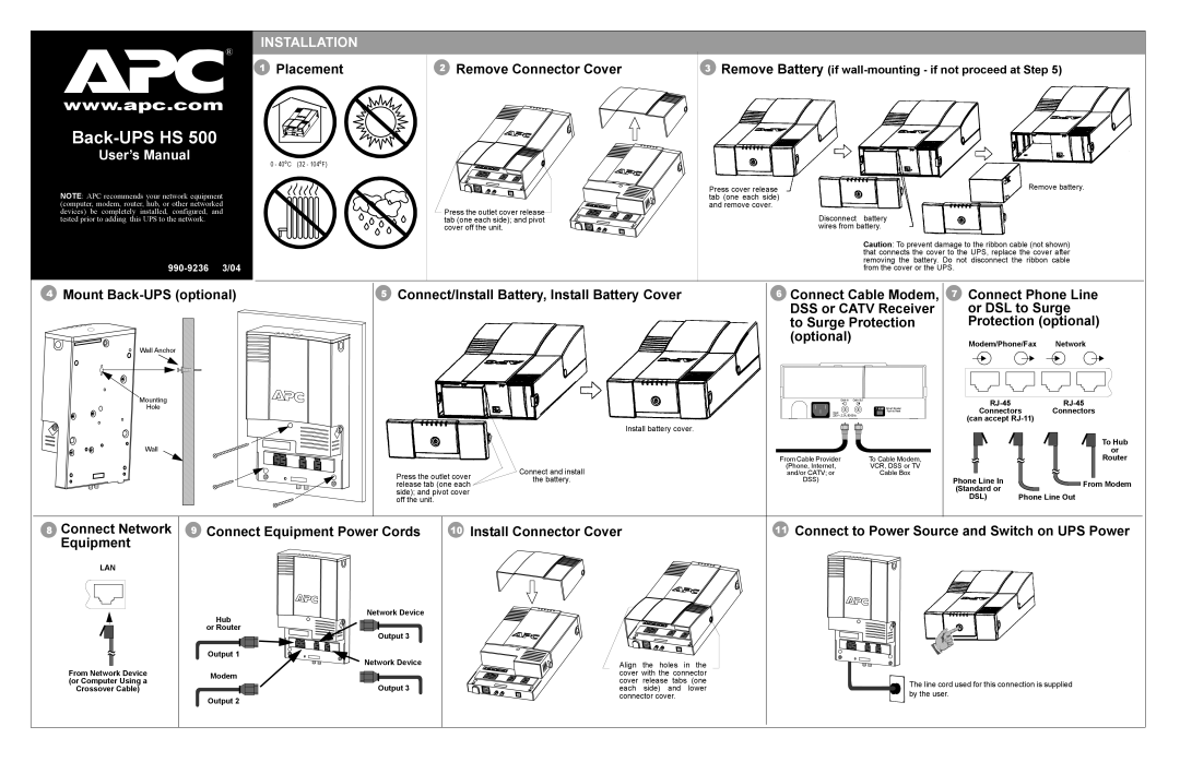
INSTALLATION
1 Placement | 2 Remove Connector Cover | 3 Remove Battery (if |
0 - 40oC (32 - 104oF)
Press cover release | Remove battery. |
tab (one each side) |
|
and remove cover. |
|
Press the outlet cover release | Disconnect battery |
tab (one each side); and pivot | |
cover off the unit. | wires from battery. |
| Caution: To prevent damage to the ribbon cable (not shown) |
| that connects the cover to the UPS, replace the cover after |
| removing the battery. Do not disconnect the ribbon cable |
| from the cover or the UPS. |
4 Mount | 5 Connect/Install Battery, Install Battery Cover | 6 Connect Cable Modem, | 7 Connect Phone Line |
|
| DSS or CATV Receiver | or DSL to Surge |
|
| to Surge Protection | Protection (optional) |
Wall Anchor |
| (optional) | Modem/Phone/Fax Network |
|
| ||
|
|
|
Mounting |
| Cable In | Cable Out |
| ||
Hole |
|
| 7 AMP Circuit Breaker |
| ||
|
| Input: | Push to Reset | Connectors | Connectors | |
|
| 230V~, 2.2A, | (can accept |
| ||
|
| Install battery cover. |
|
| ||
|
|
|
|
|
| |
Wall |
|
|
|
|
| To Hub |
|
|
|
|
| or | |
|
| From Cable Provider | To Cable Modem, |
|
| Router |
| Connect and install | (Phone, Internet, | VCR, DSS or TV |
|
|
|
Press the outlet cover | and/or CATV; or | Cable Box |
|
|
| |
the battery. | DSS) |
| Phone Line In |
| From Modem | |
release tab (one each |
|
| ||||
|
|
| (Standard or |
| ||
side); and pivot cover |
|
|
|
|
| |
|
|
| DSL) | Phone Line Out | ||
off the unit. |
|
|
| |||
8 Connect Network 9 | Connect Equipment Power Cords | 10 Install Connector Cover | 11 Connect to Power Source and Switch on UPS Power |
Equipment |
|
|
|
LAN |
|
|
|
Network Device
Hub |
or Router |
Output 3 |
| Output 1 |
|
|
|
|
| |
From Network Device | Network Device | Align the holes in the |
| ||||
Modem | cover with the connector |
| |||||
(or Computer Using a | cover | release | tabs | (one | The line cord used for this connection is supplied | ||
Output 3 | |||||||
Crossover Cable) | each | side) | and | lower | |||
by the user. | |||||||
| Output 2 | connector cover. |
| ||||
|
|
|
|
|
| ||