Revision A |
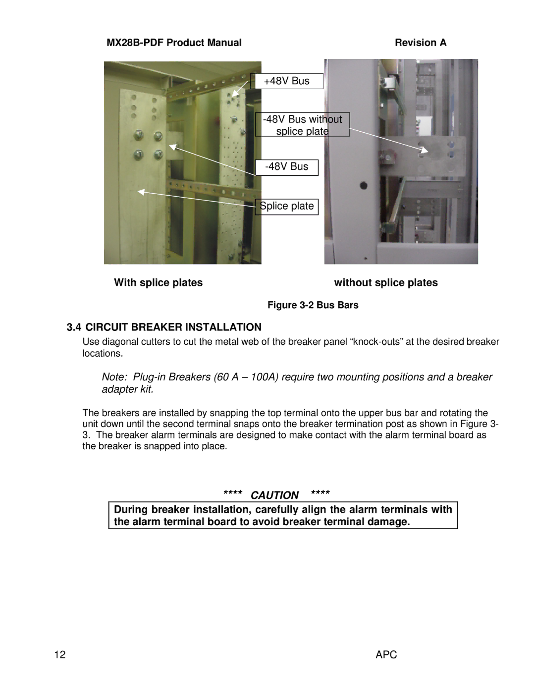
+48V Bus
splice plate
![]() Splice plate
Splice plate
With splice plates | without splice plates |
Figure 3-2 Bus Bars
3.4 CIRCUIT BREAKER INSTALLATION
Use diagonal cutters to cut the metal web of the breaker panel
Note:
The breakers are installed by snapping the top terminal onto the upper bus bar and rotating the unit down until the second terminal snaps onto the breaker termination post as shown in Figure 3-
3.The breaker alarm terminals are designed to make contact with the alarm terminal board as the breaker is snapped into place.
**** CAUTION ****
During breaker installation, carefully align the alarm terminals with the alarm terminal board to avoid breaker terminal damage.
12 | APC |
