Surge Counter Option
In units so equipped, the surge counter option provides a means to total the number of transient voltage surges encountered since the counter was last reset. The surge counter circuitry includes a “supercap”. This will provide power up to four days to retain memory should a power outage occur. NOTE: There is a 10 - 15 minute charging cycle once power is connected, before the surge counter operates. The surge counter registers the sum of
Dry Contacts Option
The PM Series is available with optional Dry Contacts which utilize a
For custom applications using the Dry Contacts, please note the following information:
•The Dry Contacts are designed for low voltage or control signals only.
•Maximum switching current is 1 amp.
•Maximum switching voltage is 24 volts, DC or AC.
Higher energy application may require additional relay implementation outside the PM. Damage to the PM’s relay caused by implementation with energy levels in excess of those discussed in this manual will not be covered by warranty. If you have design questions, please contact APC at:
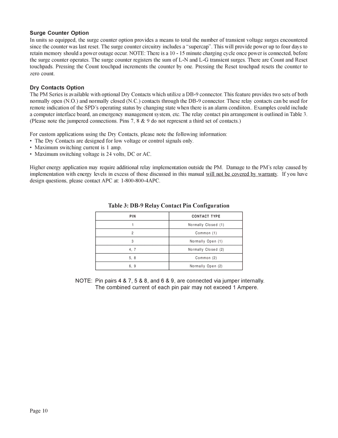
Table 3: DB-9 Relay Contact Pin Configuration
P I N | CONTACT TYP E |
|
|
1 | No rm al l y Cl o s e d (1) |
|
|
2 | Co m m o n (1) |
|
|
3 | No rm al l y Op e n (1) |
|
|
4, 7 | No rm al l y Cl o s e d (2) |
|
|
5, 8 | Co m m o n (2) |
|
|
6, 9 | No rm al l y O p e n (2) |
|
|
NOTE: Pin pairs 4 & 7, 5 & 8, and 6 & 9, are connected via jumper internally.
The combined current of each pin pair may not exceed 1 Ampere.
Page 10