Table 2: Voltage Rating and Service Type (by Model)
Model Number | Voltage Rating and Service Type |
|
|
PMP3, PMP3D, PMP4, and PMP4D | 120/240 Volts, Single Phase |
|
|
PMF3, PMF3D, PMF3S, PMF4, and PMF4D | 120/208 Volts, |
|
|
PMG3, PMG3D, PMG4, PMG4D, PMG4S, and PMG4DS | 277/480 Volts, |
|
|
PML3, PML3D, PML3S, PML4, PML4D, PML4S, PML4Y, and PML4DS | 347/600 Volts, |
|
|
Terminals
Terminals have been provided inside the APC modular SPD units for the line (phase), neutral, and equipment safety ground connections. Terminal wire size for all models is #8 AWG - #1 AWG. Installation torque is 65
System Grounding
An equipment grounding conductor must be used on all electrical circuits connected to the SPD. This requirement is primarily for safety, although SPD performance is enhanced by proper grounding. Proper operation of any surge suppression system or device depends on a proper grounding system. Incorrect grounding practices will reduce the effectiveness or interfere with SPD system operation and performance, as well as endanger personnel and equipment. For the best perfor- mance, use a single point ground system where the service entrance grounding electrode system is connected to and bonded to all other available electrodes, building steel, metal water pipes, driven rods, etc. For sensitive electronics and computer systems, it is recommended that the ground impedance measurement be 25 ohms or less. When metallic raceway is used as an additional grounding conductor, an insulated grounding conductor should be run inside the raceway. Adequate electrical continuity must be maintained at all raceway connections. Do not use isolating bushings to interrupt a metallic raceway run. A separate isolated ground for the SPD is NOT recommended. Proper equipment connections to grounding system and ground grid continuity should be verified via inspections and testing on a regular basis as part of a comprehensive electrical maintenance program.
On
installed per the NEC. Failure to do so could cause equipment damage.
Parallel Connection
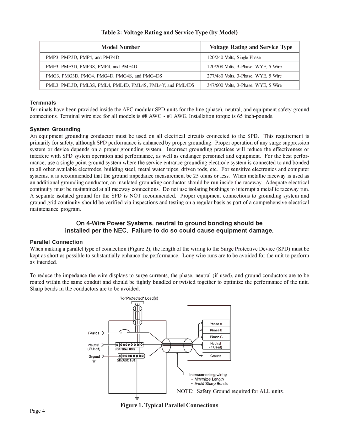
When making a parallel type of connection (Figure 2), the length of the wiring to the Surge Protective Device (SPD) must be kept as short as possible to substantially enhance the performance. Long wire runs are to be avoided for the unit to perform as intended.
To reduce the impedance the wire displays to surge currents, the phase, neutral (if used), and ground conductors are to be routed within the same conduit and should be tightly bundled or twisted together to optimize the performance of the unit. Sharp bends in the conductors are to be avoided.
NOTE: Safety Ground required for ALL units.
Figure 1. Typical Parallel Connections
Page 4