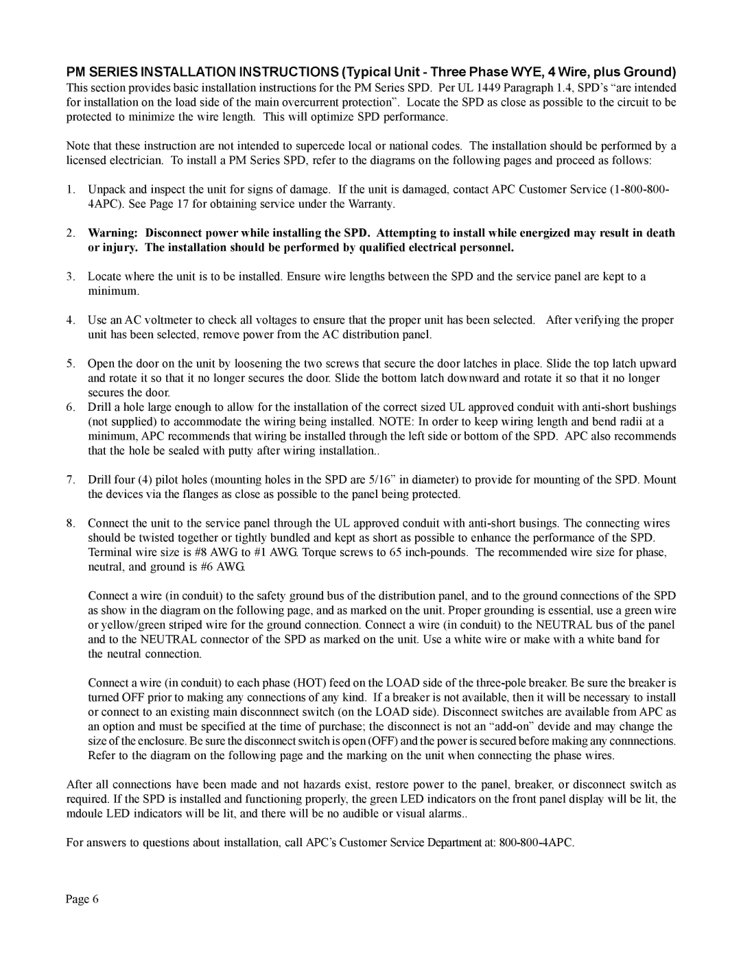
PM SERIES INSTALLATION INSTRUCTIONS (Typical Unit - Three Phase WYE, 4 Wire, plus Ground)
This section provides basic installation instructions for the PM Series SPD. Per UL 1449 Paragraph 1.4, SPD’s “are intended for installation on the load side of the main overcurrent protection”. Locate the SPD as close as possible to the circuit to be protected to minimize the wire length. This will optimize SPD performance.
Note that these instruction are not intended to supercede local or national codes. The installation should be performed by a licensed electrician. To install a PM Series SPD, refer to the diagrams on the following pages and proceed as follows:
1.Unpack and inspect the unit for signs of damage. If the unit is damaged, contact APC Customer Service
2.Warning: Disconnect power while installing the SPD. Attempting to install while energized may result in death or injury. The installation should be performed by qualified electrical personnel.
3.Locate where the unit is to be installed. Ensure wire lengths between the SPD and the service panel are kept to a minimum.
4.Use an AC voltmeter to check all voltages to ensure that the proper unit has been selected. After verifying the proper unit has been selected, remove power from the AC distribution panel.
5.Open the door on the unit by loosening the two screws that secure the door latches in place. Slide the top latch upward and rotate it so that it no longer secures the door. Slide the bottom latch downward and rotate it so that it no longer secures the door.
6.Drill a hole large enough to allow for the installation of the correct sized UL approved conduit with
7.Drill four (4) pilot holes (mounting holes in the SPD are 5/16” in diameter) to provide for mounting of the SPD. Mount the devices via the flanges as close as possible to the panel being protected.
8.Connect the unit to the service panel through the UL approved conduit with
Connect a wire (in conduit) to the safety ground bus of the distribution panel, and to the ground connections of the SPD as show in the diagram on the following page, and as marked on the unit. Proper grounding is essential, use a green wire or yellow/green striped wire for the ground connection. Connect a wire (in conduit) to the NEUTRAL bus of the panel and to the NEUTRAL connector of the SPD as marked on the unit. Use a white wire or make with a white band for the neutral connection.
Connect a wire (in conduit) to each phase (HOT) feed on the LOAD side of the
After all connections have been made and not hazards exist, restore power to the panel, breaker, or disconnect switch as required. If the SPD is installed and functioning properly, the green LED indicators on the front panel display will be lit, the mdoule LED indicators will be lit, and there will be no audible or visual alarms..
For answers to questions about installation, call APC’s Customer Service Department at:
Page 6
