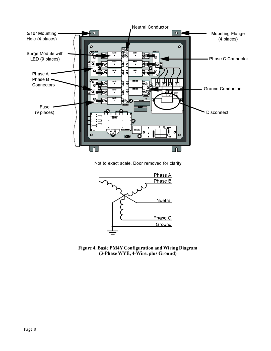
Contents
SurgeArrest PM Series
PM3, PM4, and PM4Y Series Modular Surge Protective Device SPD
User’s Manual
APC0212040A
Page
Contents
PM Series
SurgeArrest
Contents
SurgeArrest PM Series
FIGURES
High Voltage Testing - DO NOT HI-POT TEST
Please read the following installation and testing warnings
DANGER
HAZARD OF ELECTRIC SHOCK, BURN, OR EXPLOSION
Table 1 PM3, PM4, and PM4Y Dimensions and Weights
Model
VERIFY THAT ALL POWER WARNING CIRCUITS ARE DE-ENERGIZED
BEFORE MAKING CONNECTIONS
Service Clearance
Equipment Performance
Table 2 Voltage Rating and Service Type by Model
On 4-Wire Power Systems, neutral to ground bonding should be
installed per the NEC. Failure to do so could cause equipment damage
Voltage Rating and Service Type
Wiring Size & Installation Torque
Disconnect Switch
Figure 2 Basic PM Configuration with Disconnect Switch Option
Daughterboard for Optional Surge Counter Shown
Page
Figure 3 Basic PM3 and PM4 Configuration and Wiring Diagram
3-Phase WYE, 4-Wire, plus Ground
Page
Figure 4. Basic PM4Y Configuration and Wiring Diagram
3-Phase WYE, 4-Wire, plus Ground
Neutral Conductor
Figure 5. Status Panel with Surge Counter Option
Operation and Features
Status Panel Controls, Indicators and Alarms
Table 3 DB-9 Relay Contact Pin Configuration
Surge Counter Option
Dry Contacts Option
Periodic Inspection and Cleaning
Figure 6 Troubleshooting Flowchart
Page
Figure 7 Display Board Locator Diagram
Figure 8 Diagnostic Board Locator Diagram
Diagnostic Board Removal & Replacement Instructions
Models PM3 and PM4
Model PML4Y
Figure 9 Surge Module Removal and Replacement
Surge Module Removal & Replacement Instructions
Replacement Parts Listing
Table 4 Replacement Parts List
APC Model
Voltage System
LIMITED WARRANTY
Technical Support and Customer Service
Page
Page
American Power Conversion Corporation 132 Fairgrounds Road P.O. Box
West Kingston, Rhode Island 02892 USA