101 HOW TO SET DETECTION RANGE | Fig. 13 |
| |
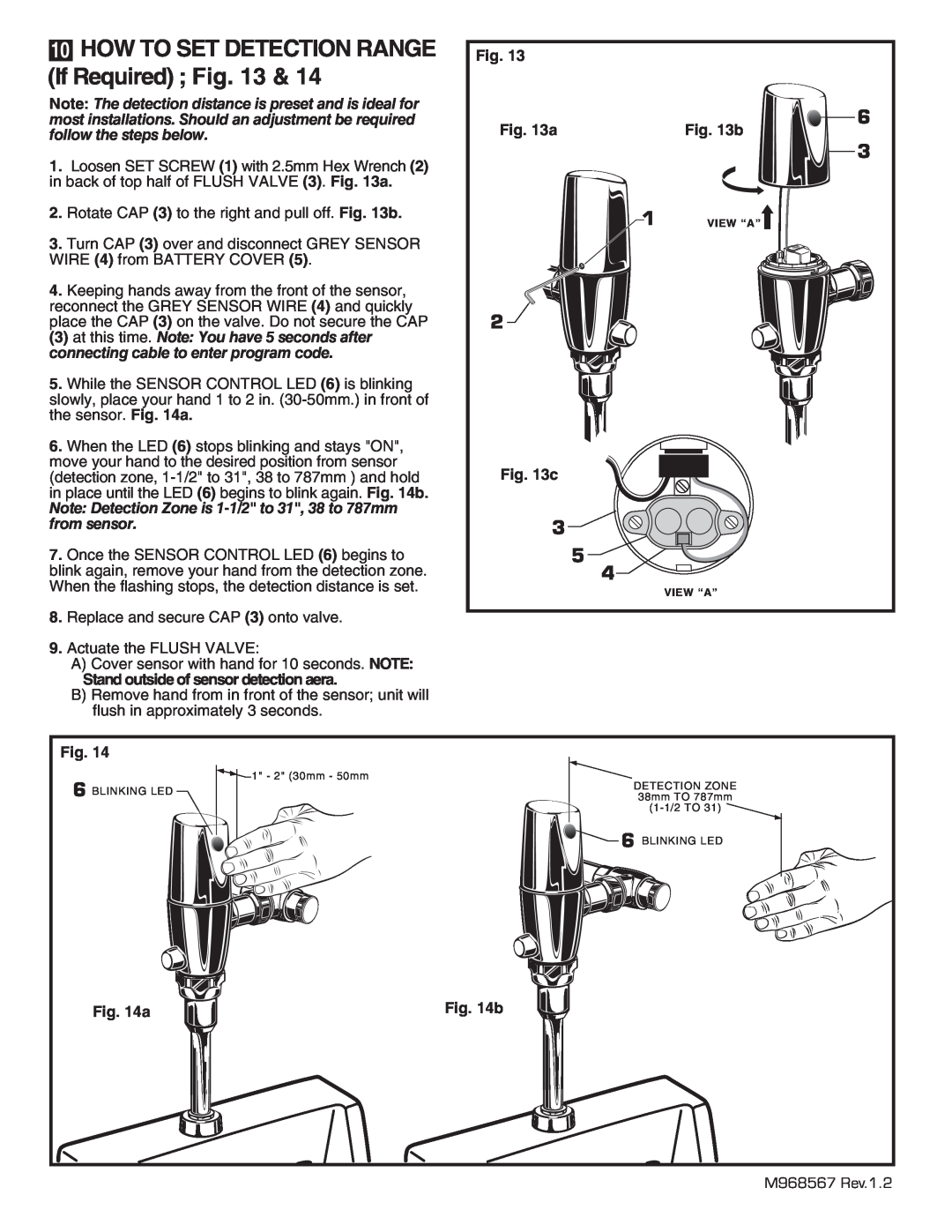
(If Required) ; Fig. 13 & 14 |
|
| |
Note: The detection distance is preset and is ideal for |
| 6 | |
most installations. Should an adjustment be required | Fig. 13a | ||
follow the steps below. | Fig. 13b | ||
| 3 | ||
1. | Loosen SET SCREW (1) with 2.5mm Hex Wrench (2) |
| |
|
| ||
in back of top half of FLUSH VALVE (3). Fig. 13a. |
|
| |
2. | Rotate CAP (3) to the right and pull off. Fig. 13b. | 1 | VIEW “A” |
3. | Turn CAP (3) over and disconnect GREY SENSOR |
|
|
WIRE (4) from BATTERY COVER (5). |
|
| |
4. | Keeping hands away from the front of the sensor, |
|
|
reconnect the GREY SENSOR WIRE (4) and quickly | 2 |
| |
place the CAP (3) on the valve. Do not secure the CAP |
| ||
(3) at this time. Note: You have 5 seconds after |
|
| |
connecting cable to enter program code. |
|
| |
5. | While the SENSOR CONTROL LED (6) is blinking |
|
|
slowly, place your hand 1 to 2 in. |
|
| |
the sensor. Fig. 14a. |
|
| |
6. | When the LED (6) stops blinking and stays "ON", |
|
|
move your hand to the desired position from sensor | Fig. 13c |
| |
(detection zone, |
| ||
in place until the LED (6) begins to blink again. Fig. 14b. |
|
| |
Note: Detection Zone is |
|
| |
from sensor. | 3 |
| |
7. | Once the SENSOR CONTROL LED (6) begins to | 5 |
|
blink again, remove your hand from the detection zone. | 4 |
| |
When the flashing stops, the detection distance is set. |
| VIEW “A” | |
|
|
| |
8. | Replace and secure CAP (3) onto valve. |
|
|
9. | Actuate the FLUSH VALVE: |
|
|
| A) Cover sensor with hand for 10 seconds. NOTE: |
|
|
| Stand outside of sensor detection aera. |
|
|
| B) Remove hand from in front of the sensor; unit will |
|
|
| flush in approximately 3 seconds. |
|
|
Fig. 14 |
|
| |
| 1" - 2" (30mm - 50mm | DETECTION ZONE | |
| 6 BLINKING LED | ||
| 38mm TO 787mm | ||
|
| ||
|
| 6 BLINKING LED | |
Fig. 14a | Fig. 14b |
M968567 Rev.1.2