AMERI*CAN TELECOM INC.
Technical Document
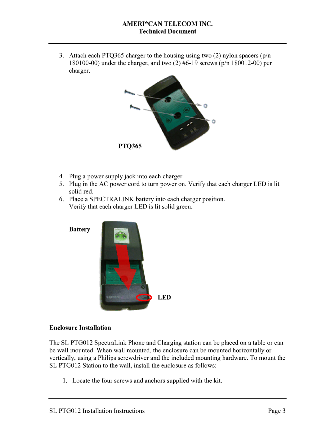
3.Attach each PTQ365 charger to the housing using two (2) nylon spacers (p/n
PTQ365
4.Plug a power supply jack into each charger.
5.Plug in the AC power cord to turn power on. Verify that each charger LED is lit solid red.
6.Place a SPECTRALINK battery into each charger position. Verify that each charger LED is lit solid green.
Battery
LED
Enclosure Installation
The SL PTG012 SpectraLink Phone and Charging station can be placed on a table or can be wall mounted. When wall mounted, the enclosure can be mounted horizontally or vertically, using a Philips screwdriver and the included mounting hardware. To mount the SL PTG012 Station to the wall, install the enclosure as follows:
1. Locate the four screws and anchors supplied with the kit.
SL PTG012 Installation Instructions | Page 3 |
