American Water Heater Commercial Ultra Low NOx Gas water Heater Temperature Regulation, Danger

Models: BBCN375T754NV Commercial Ultra Low NOx Gas water Heater

1 24
Download 24 pages 4.28 Kb
Page 11
Image 11
TEMPERATURE REGULATION

TEMPERATURE REGULATION

 DANGER DANGER

THIS WATER HEATER IS EQUIPPED WITH AN ADJUSTABLE THERMOSTAT TO CONTROL WATER TEMPERATURE. HOT WATER TEMPERATURES REQUIRED FOR AUTOMATIC DISHWASHING AND LAUNDRY USE CAN CAUSE PAINFUL SCALDING WITH POSSIBLE SERIOUS AND PERMANENT INJURY. THE TEMPERATURE AT WHICH INJURY OCCURS VARIES WITH THE PERSON’S AGE AND THE TIME OF THE EXPOSURE. THE SLOWER RESPONSE TIME OF CHILDREN, AGED OR DISABLED PERSONS INCREASES THE HAZARDS TO THEM. NEVER ALLOW SMALL CHILDREN TO USE A HOT WATER TAP, OR TO DRAW THEIR OWN BATH WATER. NEVER LEAVE A CHILD OR DISABLED PERSON UNATTENDED IN A BATHTUB OR SHOWER.

THE WATER HEATER SHOULD BE LOCATED IN AN AREA WHERE THE GENERAL PUBLIC DOES NOT HAVE ACCESS. IF A SUITABLE AREA IS NOT AVAILABLE, A COVER SHOULD BE INSTALLED OVER THE THERMOSTAT TO PREVENT TAMPERING.Suitable covers are available from the manufacturer, authorized service agencies or distributors. When ordering parts be sure to have the complete water heater Model Number, Serial Number and Series Number available. This information can be found on the rating label affixed to the water heater.

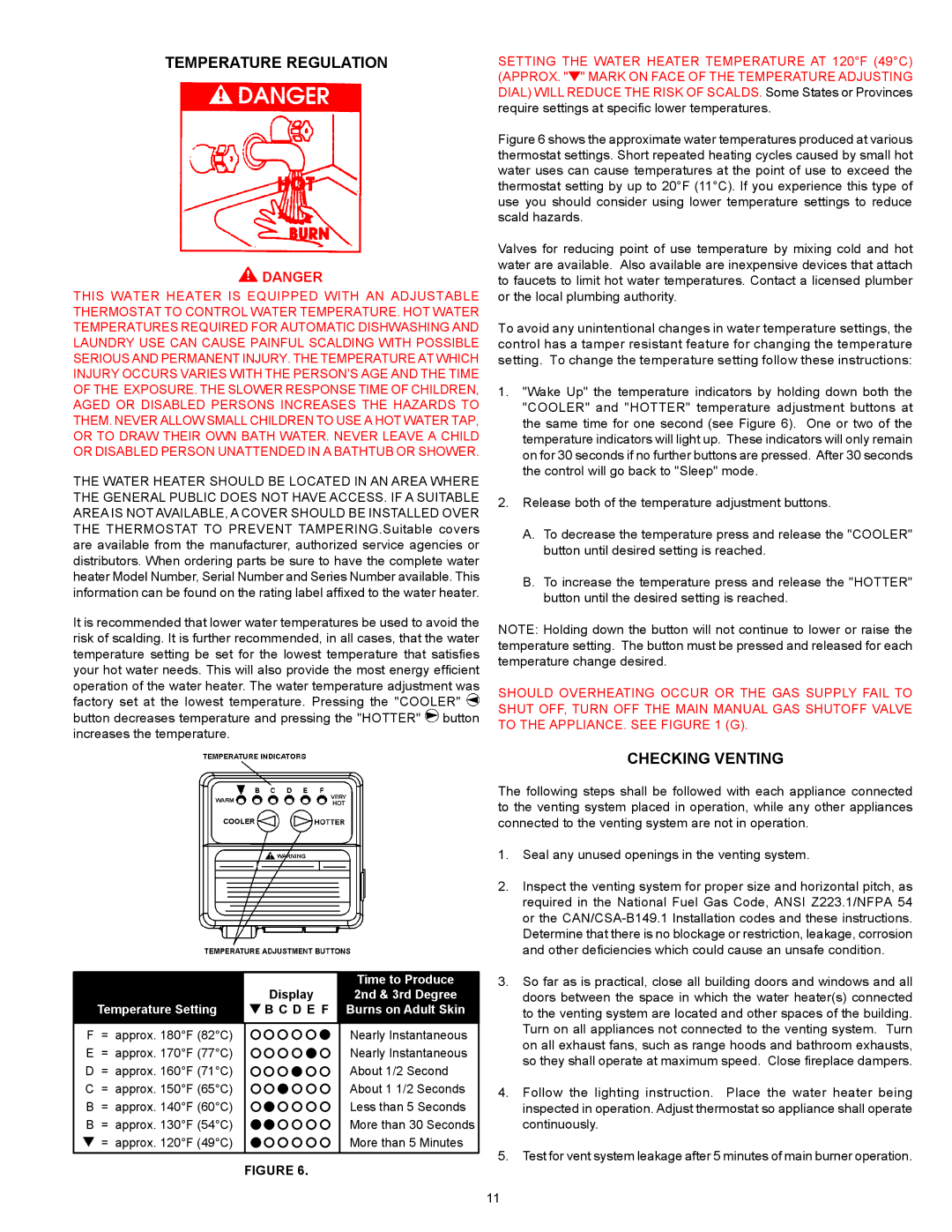
It is recommended that lower water temperatures be used to avoid the risk of scalding. It is further recommended, in all cases, that the water temperature setting be set for the lowest temperature that satisfies your hot water needs. This will also provide the most energy efficient operation of the water heater. The water temperature adjustment was factory set at the lowest temperature. Pressing the "COOLER" Time to Produce button decreases temperature and pressing the "HOTTER" Display button increases the temperature.


Time to Produce


Display

2nd & 3rd Degree

Temperature Setting

B C D E F

Burns on Adult Skin


SETTING THE WATER HEATER TEMPERATURE AT 120°F (49°C)

(APPROX. "Temperature Setting" MARK ON FACE OF THE TEMPERATURE ADJUSTING DIAL) WILL REDUCE THE RISK OF SCALDS. Some States or Provinces require settings at specific lower temperatures.

Figure 6 shows the approximate water temperatures produced at various thermostat settings. Short repeated heating cycles caused by small hot water uses can cause temperatures at the point of use to exceed the thermostat setting by up to 20°F (11°C). If you experience this type of use you should consider using lower temperature settings to reduce scald hazards.

Valves for reducing point of use temperature by mixing cold and hot water are available. Also available are inexpensive devices that attach to faucets to limit hot water temperatures. Contact a licensed plumber or the local plumbing authority.

To avoid any unintentional changes in water temperature settings, the control has a tamper resistant feature for changing the temperature setting. To change the temperature setting follow these instructions:

1."Wake Up" the temperature indicators by holding down both the "COOLER" and "HOTTER" temperature adjustment buttons at the same time for one second (see Figure 6). One or two of the temperature indicators will light up. These indicators will only remain on for 30 seconds if no further buttons are pressed. After 30 seconds the control will go back to "Sleep" mode.

2.Release both of the temperature adjustment buttons.

A.To decrease the temperature press and release the "COOLER" button until desired setting is reached.

B.To increase the temperature press and release the "HOTTER" button until the desired setting is reached.

NOTE: Holding down the button will not continue to lower or raise the temperature setting. The button must be pressed and released for each temperature change desired.

SHOULD OVERHEATING OCCUR OR THE GAS SUPPLY FAIL TO SHUT OFF, TURN OFF THE MAIN MANUAL GAS SHUTOFF VALVE TO THE APPLIANCE. SEE FIGURE 1 (G).

CHECKING VENTING

The following steps shall be followed with each appliance connected to the venting system placed in operation, while any other appliances connected to the venting system are not in operation.

1.

Seal any unused openings in the venting system.

2.

Inspect the venting system for proper size and horizontal pitch, as


required in the National Fuel Gas Code, ANSI Z223.1/NFPA 54


or the CAN/CSA-B149.1 Installation codes and these instructions.


Determine that there is no blockage or restriction, leakage, corrosion


and other deficiencies which could cause an unsafe condition.

3.

So far as is practical, close all building doors and windows and all


doors between the space in which the water heater(s) connected


to the venting system are located and other spaces of the building.


Turn on all appliances not connected to the venting system. Turn

F= approx. 180°F (82°C) E = approx. 170°F (77°C) D = approx. 160°F (71°C) C = approx. 150°F (65°C) B = approx. 140°F (60°C) B = approx. 130°F (54°C)

= approx. 120°F (49°C)

Nearly Instantaneous Nearly Instantaneous About 1/2 Second About 1 1/2 Seconds Less than 5 Seconds More than 30 Seconds More than 5 Minutes


on all exhaust fans, such as range hoods and bathroom exhausts,


so they shall operate at maximum speed. Close fireplace dampers.

4.

Follow the lighting instruction. Place the water heater being


inspected in operation. Adjust thermostat so appliance shall operate


continuously.

5.

Test for vent system leakage after 5 minutes of main burner operation.

FIGURE 6.

11

Page 11
Image 11
American Water Heater Commercial Ultra Low NOx Gas water Heater Temperature Regulation, Checking Venting, Danger, Display