B500DR specifications
The Ampeg B500DR is a powerful and versatile bass amplifier, designed to provide bassists with superior sound quality, performance, and reliability. With its rich heritage rooted in the history of bass amplification, the B500DR is part of Ampeg’s legendary line-up, ensuring that it meets the high demands of both live performances and studio recordings.One of the standout features of the B500DR is its robust 500-watt output, which delivers enough power to handle virtually any performance situation. This amp is equipped with a 4-band EQ section, allowing bassists to shape their tone with precision. The EQ comprises frequency controls for low, low-mid, high-mid, and treble, providing a wide range of tonal possibilities. The addition of a built-in compressor further enhances its capabilities, allowing players to maintain dynamic control, producing a tight and punchy sound.
The B500DR utilizes Ampeg's innovative tube preamp technology, which imbues the sound with warmth and character that solid-state amps often lack. The use of 12AX7 tubes gives the amplifier a classic tonal quality that bassists crave. This, coupled with a solid-state power section, ensures that the amp can deliver both the richness of tube sound and the reliability of solid-state performance.
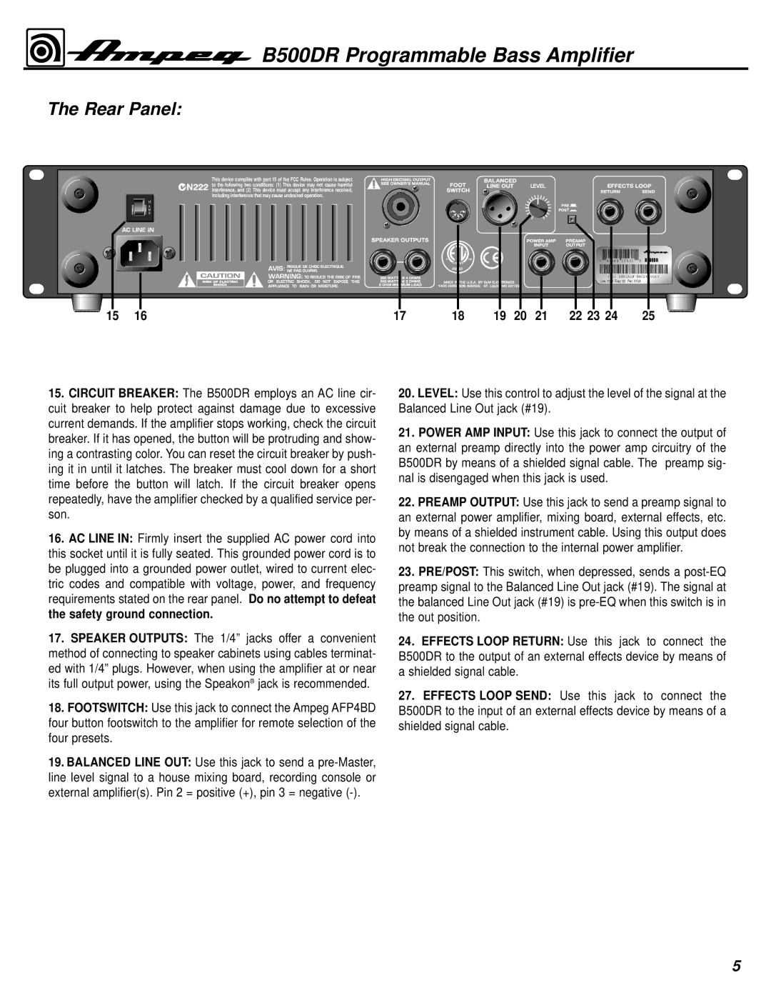
Another notable feature is the Rear panel's versatile connectivity options, including XLR direct outputs, allowing for easy integration into any live or recording environment. The headphone output is perfect for practicing silently without disturbing others. Additionally, the B500DR is equipped with an auxiliary input, making it easy for players to jam along with their favorite tracks.
The B500DR's rugged construction is designed to withstand the rigors of touring. Its durable enclosure and high-quality components ensure it can handle the stresses of frequent transport. The flexible cabinet design allows it to pair well with a variety of speaker cabinets, providing even more sound options.
In conclusion, the Ampeg B500DR is a comprehensive solution for bassists looking for a powerful, flexible amplifier that doesn't compromise on tone or performance. With its advanced features, reliable technology, and exceptional sound quality, the B500DR stands out as a top choice among both professional and aspiring bass players alike. Whether on stage or in the studio, this amplifier is built to impress and deliver the goods.

