Installation
Installation
Setting the DEVICE DIP Switch
The
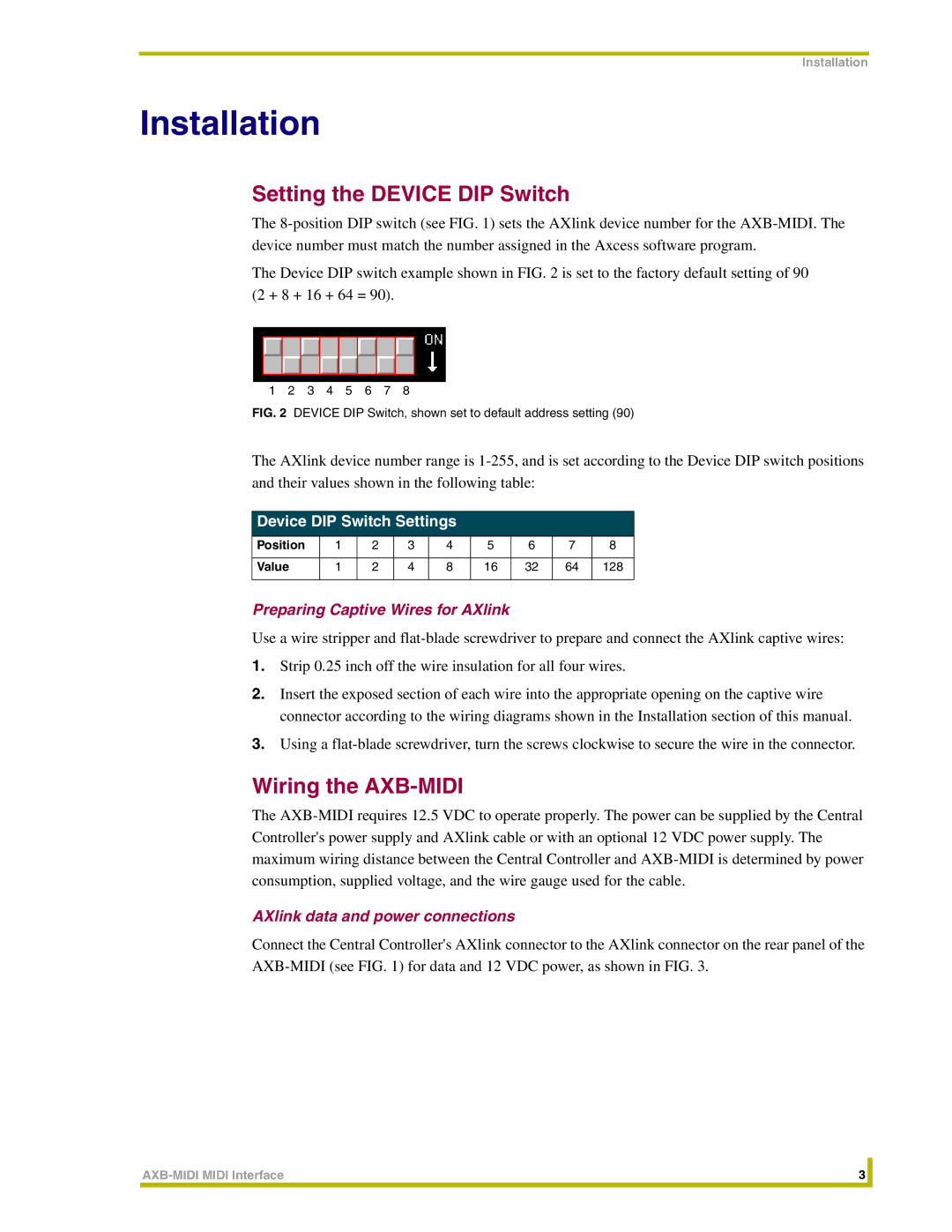
The Device DIP switch example shown in FIG. 2 is set to the factory default setting of 90 (2 + 8 + 16 + 64 = 90).
1 2 3 4 5 6 7 8
FIG. 2 DEVICE DIP Switch, shown set to default address setting (90)
The AXlink device number range is
Device DIP Switch Settings
Position | 1 | 2 | 3 | 4 | 5 | 6 | 7 | 8 |
|
|
|
|
|
|
|
|
|
Value | 1 | 2 | 4 | 8 | 16 | 32 | 64 | 128 |
|
|
|
|
|
|
|
|
|
Preparing Captive Wires for AXlink
Use a wire stripper and
1.Strip 0.25 inch off the wire insulation for all four wires.
2.Insert the exposed section of each wire into the appropriate opening on the captive wire connector according to the wiring diagrams shown in the Installation section of this manual.
3.Using a
Wiring the AXB-MIDI
The
AXlink data and power connections
Connect the Central Controller's AXlink connector to the AXlink connector on the rear panel of the
3 |
| |
|
|
|