Connection and Wiring
Connection and Wiring
Setting the DEVICE Dip Switch
The
If you later change the device number, remove and reconnect the AXlink connector. This enters the new device number into memory. The device number takes effect only on
The device can be 1 of the 255 devices in an Axcess, AXCENT, AXCENT2, or AXCENT3 system. The device number must match the device assignment in the Axcess program. AMX assigns device numbers into the following three segments:
! | Cards | 1 through 95 |
|
! | Boxes | 96 through 127 | |
! | Panels | 128 through | 255 |
Set the device number by setting the DEVICE DIP switch. The device number is the total of all of the switches in the ON (down) position. The following table shows the switch numbers and their corresponding values.
Device DIP switch settings
Position | 1 | 2 | 3 | 4 | 5 | 6 | 7 | 8 |
|
|
|
|
|
|
|
|
|
Value | 1 | 2 | 4 | 8 | 16 | 32 | 64 | 128 |
|
|
|
|
|
|
|
|
|
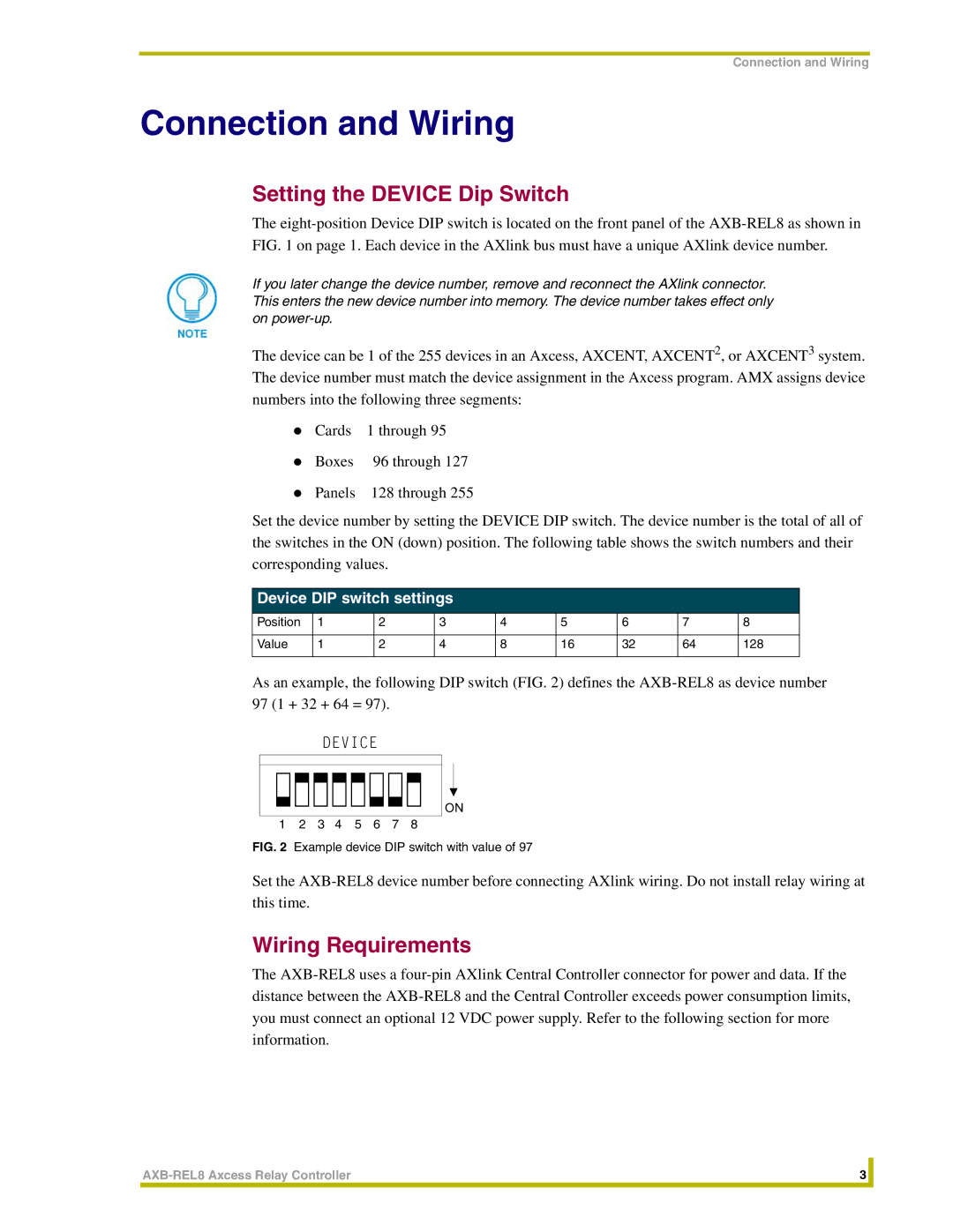
As an example, the following DIP switch (FIG. 2) defines the
DEVICE
ON
1 2 3 4 5 6 7 8
FIG. 2 Example device DIP switch with value of 97
Set the
Wiring Requirements
The
3 |
| |
|
|
|