Connection and Wiring
A
1 |
|
B |
|
A |
|
2 |
|
B |
|
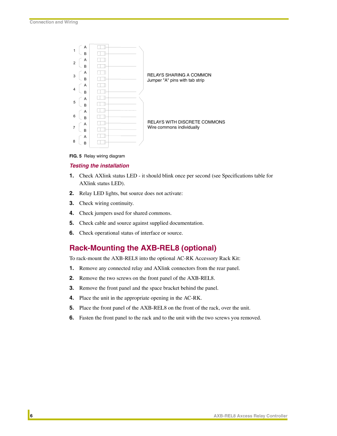
A | RELAYS SHARING A COMMON |
3 | |
B | Jumper "A" pins with tab strip |
A
4 | B | |
| ||
5 | A | |
B | ||
| ||
| A |
6B
| A | RELAYS WITH DISCRETE COMMONS | |
7 | Wire commons individually | ||
B | |||
|
|
A
8B
FIG. 5 Relay wiring diagram
Testing the installation
1.Check AXlink status LED - it should blink once per second (see Specifications table for AXlink status LED).
2.Relay LED lights, but source does not activate:
3.Check wiring continuity.
4.Check jumpers used for shared commons.
5.Check cable and source against supplied documentation.
6.Check operational status of interface or source.
Rack-Mounting the AXB-REL8 (optional)
To
1.Remove any connected relay and AXlink connectors from the rear panel.
2.Remove the two screws on the front panel of the
3.Remove the front panel and the space bracket behind the panel.
4.Place the unit in the appropriate opening in the
5.Place the front panel of the
6.Fasten the front panel to the rack and to the unit with the two screws you removed.
| 6 | |
|
|
|
