Connection and Wiring
AXlink data and power connections
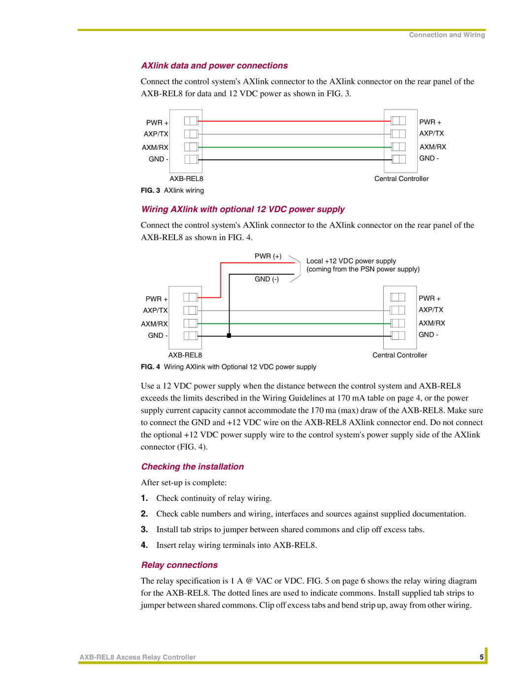
Connect the control system's AXlink connector to the AXlink connector on the rear panel of the
PWR + |
|
|
|
|
|
|
|
|
|
| PWR + |
|
|
|
|
|
|
|
|
|
| ||
|
|
|
|
|
|
|
|
|
| ||
AXP/TX |
|
|
|
|
|
|
|
|
|
| AXP/TX |
|
|
|
|
|
|
|
|
|
| ||
|
|
|
|
|
|
|
|
|
| ||
AXM/RX |
|
|
|
|
|
|
|
|
|
| AXM/RX |
|
|
|
|
|
|
|
|
|
| ||
|
|
|
|
|
|
|
|
|
| ||
GND - |
|
|
|
|
|
|
|
|
|
| GND - |
|
|
|
|
|
|
|
|
|
| ||
|
|
|
|
|
|
|
|
|
| ||
|
|
|
|
|
|
|
|
|
|
|
|
|
| Central Controller | |||||||||
FIG. 3 AXlink wiring |
|
|
|
|
|
| |||||
Wiring AXlink with optional 12 VDC power supply
Connect the control system's AXlink connector to the AXlink connector on the rear panel of the
|
|
|
|
|
|
|
|
| PWR (+) | |||||||
|
|
|
|
|
|
|
|
|
|
| Local +12 VDC power supply | |||||
|
|
|
|
|
|
|
|
|
|
| (coming from the PSN power supply) | |||||
|
|
|
|
|
|
|
|
|
|
| ||||||
|
|
|
|
|
|
|
|
| GND | |||||||
|
|
|
|
|
|
|
|
|
|
|
|
|
|
|
| PWR + |
PWR + |
|
|
|
|
|
|
|
|
|
|
|
|
|
|
| |
|
|
|
|
|
|
|
|
|
|
|
|
|
|
| ||
|
|
|
|
|
|
|
|
|
|
|
|
|
|
| ||
AXP/TX |
|
|
|
|
|
|
|
|
|
|
|
|
|
|
| AXP/TX |
|
|
|
|
|
|
|
|
|
|
|
|
|
|
| ||
|
|
|
|
|
|
|
|
|
|
|
|
|
|
| ||
AXM/RX |
|
|
|
|
|
|
|
|
|
|
|
|
|
|
| AXM/RX |
|
|
|
|
|
|
|
|
|
|
|
|
|
|
| ||
|
|
|
|
|
|
|
|
|
|
|
|
|
|
| ||
GND - |
|
|
|
|
|
|
|
|
|
|
|
|
|
|
| GND - |
|
|
|
|
|
|
|
|
|
|
|
|
|
|
|
|
|
|
|
|
|
|
| Central Controller | ||||||||||
FIG. 4 Wiring AXlink with Optional 12 VDC power supply
Use a 12 VDC power supply when the distance between the control system and
Checking the installation
After
1.Check continuity of relay wiring.
2.Check cable numbers and wiring, interfaces and sources against supplied documentation.
3.Install tab strips to jumper between shared commons and clip off excess tabs.
4.Insert relay wiring terminals into
Relay connections
The relay specification is 1 A @ VAC or VDC. FIG. 5 on page 6 shows the relay wiring diagram for the
5 |
| |
|
|
|
