Product Information
Specifications (Cont.)
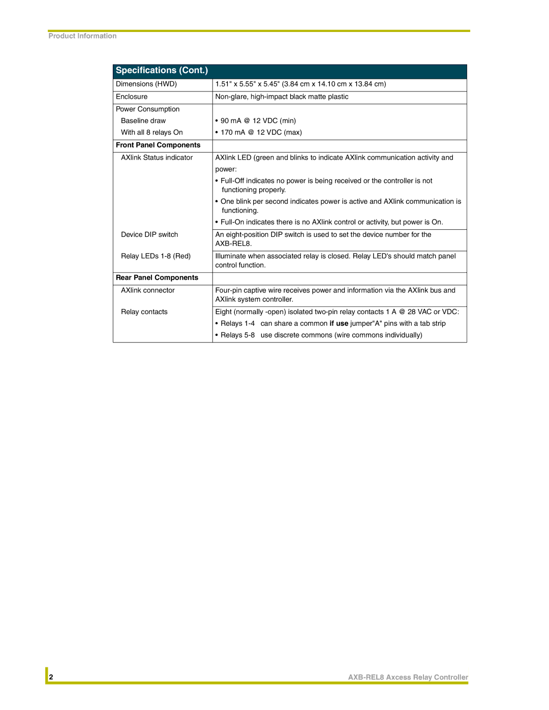
Dimensions (HWD) | 1.51" x 5.55" x 5.45" (3.84 cm x 14.10 cm x 13.84 cm) |
|
|
Enclosure | |
|
|
Power Consumption |
|
Baseline draw | • 90 mA @ 12 VDC (min) |
With all 8 relays On | • 170 mA @ 12 VDC (max) |
|
|
Front Panel Components |
|
|
|
AXlink Status indicator | AXlink LED (green and blinks to indicate AXlink communication activity and |
| power: |
| • |
| functioning properly. |
| • One blink per second indicates power is active and AXlink communication is |
| functioning. |
| • |
|
|
Device DIP switch | An |
|
|
|
|
Relay LEDs | Illuminate when associated relay is closed. Relay LED's should match panel |
| control function. |
|
|
Rear Panel Components |
|
|
|
AXlink connector | |
| AXlink system controller. |
|
|
Relay contacts | Eight (normally |
| • Relays |
| • Relays |
|
|
| 2 | |
|
|
|