Inserting the Lithium-Ion Battery into The Mio R-3
To install your Lithium-Ion battery into the Mio R-3 remote:
1.Flip and turn the device so that the buttons are facing away from you and the device is upside down.
2.Holding the device in both hands, place your thumbs on the battery door and slide the battery door free. The battery door should slide toward the bottom end of the device.
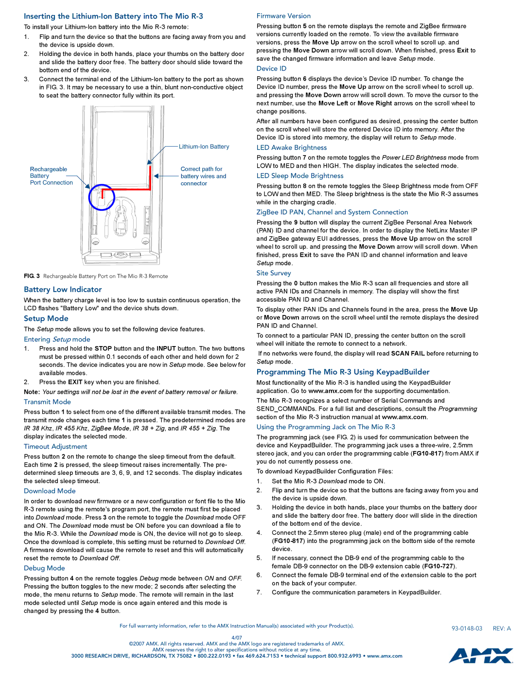
3.Connect the terminal end of the Lithium-Ion battery to the port as shown in FIG. 3. It may be necessary to use a thin, blunt non-conductive object to seat the battery connector fully within its port.
| Lithium-Ion Battery |
Rechargeable | Correct path for |
Battery | battery wires and |
Port Connection | connector |
FIG. 3 Rechargeable Battery Port on The Mio R-3 Remote
Battery Low Indicator
When the battery charge level is too low to sustain continuous operation, the LCD flashes "Battery Low" and the device shuts down.
Setup Mode
The Setup mode allows you to set the following device features.
Entering Setup mode
1.Press and hold the STOP button and the INPUT button. The two buttons must be pressed within 0.1 seconds of each other and held down for 2 seconds. The device indicates you are now in Setup mode. See below for available modes.
2.Press the EXIT key when you are finished.
Note: Your settings will not be lost in the event of battery removal or failure.
Transmit Mode
Press button 1 to select from one of the different available transmit modes. The transmit mode changes each time 1 is pressed. The predetermined modes are IR 38 Khz, IR 455 Khz, ZigBee Mode, IR 38 + Zig, and IR 455 + Zig. The display indicates the selected mode.
Timeout Adjustment
Press button 2 on the remote to change the sleep timeout from the default. Each time 2 is pressed, the sleep timeout raises incrementally. The pre- determined sleep timeouts are 3, 6, 9, and 12 seconds. The display indicates the selected sleep timeout.
Download Mode
In order to download new firmware or a new configuration or font file to the Mio R-3 remote using the remote's program port, the remote must first be placed into Download mode. Press 3 on the remote to toggle the Download mode OFF and ON. The Download mode must be ON before you can download a file to the Mio R-3. While the Download mode is ON, the device will not go to sleep. Once the download is complete, this setting must be returned to Download Off. A firmware download will cause the remote to reset and this will automatically reset the remote to Download Off.
Debug Mode
Pressing button 4 on the remote toggles Debug mode between ON and OFF. Pressing the button toggles to the new mode; 2 seconds after selecting the mode, the menu returns to Setup mode. The remote will remain in the last mode selected until Setup mode is once again entered and this mode is changed by pressing the 4 button.
Firmware Version
Pressing button 5 on the remote displays the remote and ZigBee firmware versions currently loaded on the remote. To view the available firmware versions, press the Move Up arrow on the scroll wheel to scroll up. and pressing the Move Down arrow will scroll down. When finished, press Exit to save the changed firmware information and leave Setup mode.
Device ID
Pressing button 6 displays the device’s Device ID number. To change the Device ID number, press the Move Up arrow on the scroll wheel to scroll up. and pressing the Move Down arrow will scroll down. To move the cursor to the next number, use the Move Left or Move Right arrows on the scroll wheel to change positions.
After all numbers have been configured as desired, pressing the center button on the scroll wheel will store the entered Device ID into memory. After the Device ID is stored into memory, the display will return to Setup mode.
LED Awake Brightness
Pressing button 7 on the remote toggles the Power LED Brightness mode from LOW to MED and then HIGH. The display indicates the selected mode.
LED Sleep Mode Brightness
Pressing button 8 on the remote toggles the Sleep Brightness mode from OFF to LOW and then MED. The Sleep brightness is the state the Mio R-3 assumes while in the charging cradle.
ZigBee ID PAN, Channel and System Connection
Pressing the 9 button will display the current ZigBee Personal Area Network (PAN) ID and channel for the device. In order to display the NetLinx Master IP and ZigBee gateway EUI addresses, press the Move Up arrow on the scroll wheel to scroll up. and pressing the Move Down arrow will scroll down. When finished, press Exit to save the PAN ID and channel information and leave Setup mode.
Site Survey
Pressing the 0 button makes the Mio R-3 scan all frequencies and store all active PAN IDs and Channels in memory. The display will show the first accessible PAN ID and Channel.
To display other PAN IDs and Channels found in the area, press the Move Up or Move Down arrows on the scroll wheel until the remote displays the desired PAN ID and Channel.
To connect to a particular PAN ID, pressing the center button on the scroll wheel will initiate the remote to connect to a network.
If no networks were found, the display will read SCAN FAIL before returning to Setup mode.
Programming The Mio R-3 Using KeypadBuilder
Most functionality of the Mio R-3 is handled using the KeypadBuilder application. Go to www.amx.com for the supporting documentation.
The Mio R-3 recognizes a select number of Serial Commands and
SEND_COMMANDs. For a full list and descriptions, consult the Programming section of the Mio R-3 instruction manual at www.amx.com.
Using the Programming Jack on The Mio R-3
The programming jack (see FIG. 2) is used for communication between the device and KeypadBuilder. The programming jack uses a three-wire, 2.5mm stereo jack, and you can order the programming cable (FG10-817) from AMX if you do not currently possess one.
To download KeypadBuilder Configuration Files:
1.Set the Mio R-3 Download mode to ON.
2.Flip and turn the device so that the buttons are facing away from you and the device is upside down.
3.Holding the device in both hands, place your thumbs on the battery door and slide the battery door free. The battery door will slide in the direction of the bottom end of the device.
4.Connect the 2.5mm stereo plug (male) end of the programming cable
(FG10-817) into the programming jack on the bottom side of the remote device.
5.If necessary, connect the DB-9 end of the programming cable to the female DB-9 connector on the DB-9 extension cable (FG10-727).
6.Connect the female DB-9 terminal end of the extension cable to the port on the back of your computer.
7.Configure the communication parameters in KeypadBuilder.