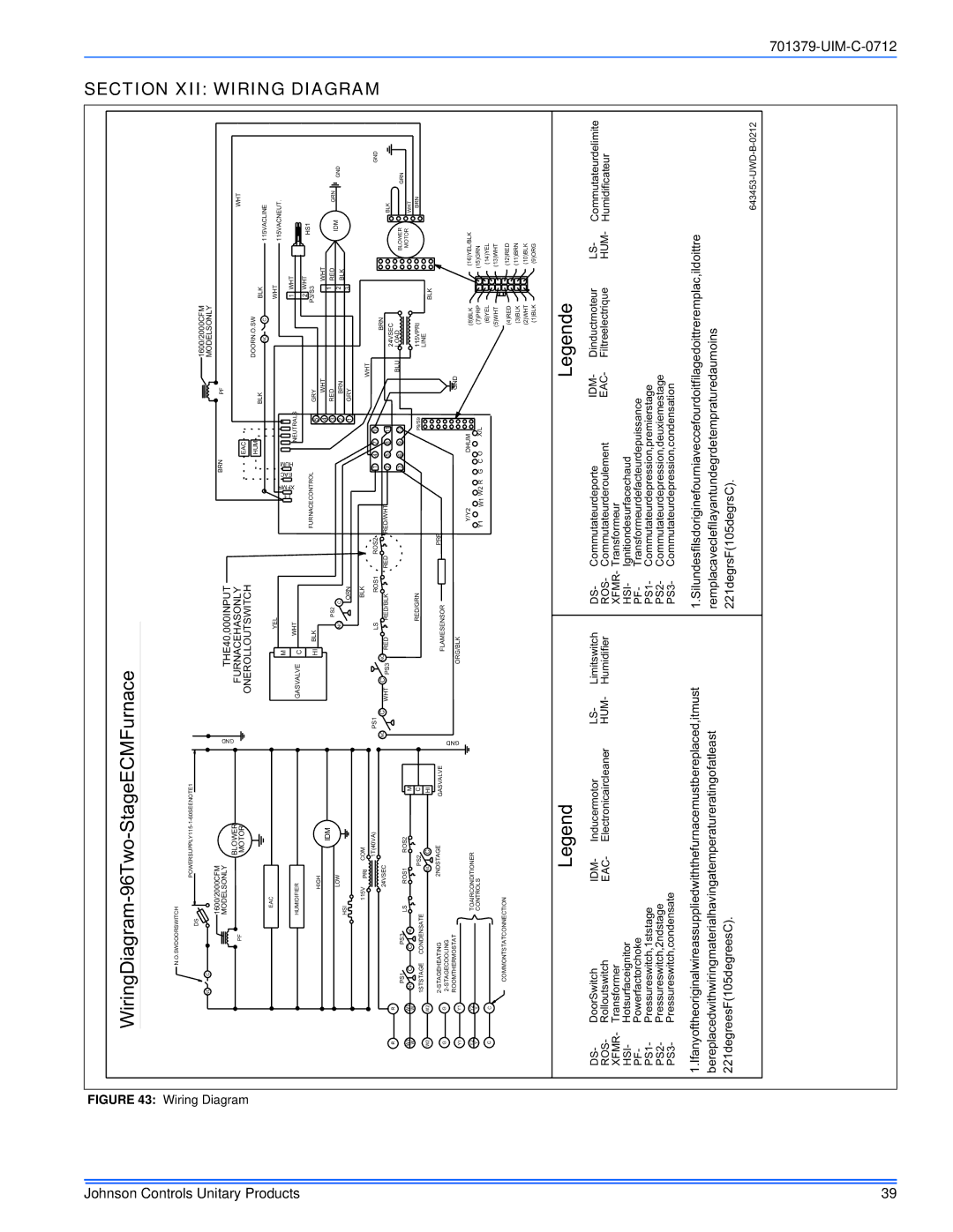
TM9V*MP specifications
Johnson Controls has long been a leader in providing innovative comfort solutions, and their TM9V*MP series of variable speed air handlers is a testament to their commitment to efficiency and performance. These products are designed to optimize heating and cooling in both residential and commercial applications, ensuring superior indoor air quality and comfort year-round.One of the standout features of the TM9V*MP series is its variable speed technology. Unlike traditional single-speed systems, the TM9V*MP adjusts its airflow according to real-time heating and cooling demands. This not only enhances comfort by maintaining consistent temperatures but also significantly reduces energy consumption. The variable speed motor operates quietly and efficiently, making it ideal for both living environments and workplaces.
In terms of design, the TM9V*MP is engineered for ease of installation and maintenance. It comes in a compact size that allows for flexible positioning within existing ductwork, making retrofits simpler for contractors. Additionally, the modular design allows for easy access to internal components, which facilitates hassle-free servicing and maintenance.
The unit also features a robust filtration system that works in tandem with a range of air quality technologies. This includes optional media filters that capture allergens and particulates, ensuring that the air quality within a space is not only comfortable but also healthy. The integration of advanced technologies, such as integrated Wi-Fi capabilities, provides users with the ability to monitor and adjust settings remotely via smartphones or tablets.
Moreover, the TM9V*MP series is compatible with a wide range of communication protocols, enabling seamless connectivity with smart home systems. This means that users can create customized comfort profiles and take advantage of energy-saving features automatically.
Durability is another key characteristic of the TM9V*MP series. Built with high-quality materials and subjected to rigorous testing, these air handlers are designed to endure even the most demanding conditions while providing reliable performance over time.
In summary, Johnson Controls' TM9V*MP series offers an array of features that cater to modern comfort demands. With its variable speed technology, user-friendly design, air quality enhancements, and strong connectivity options, it stands out as a prime choice for both residential and commercial HVAC applications, setting a high standard for efficiency and indoor comfort.

