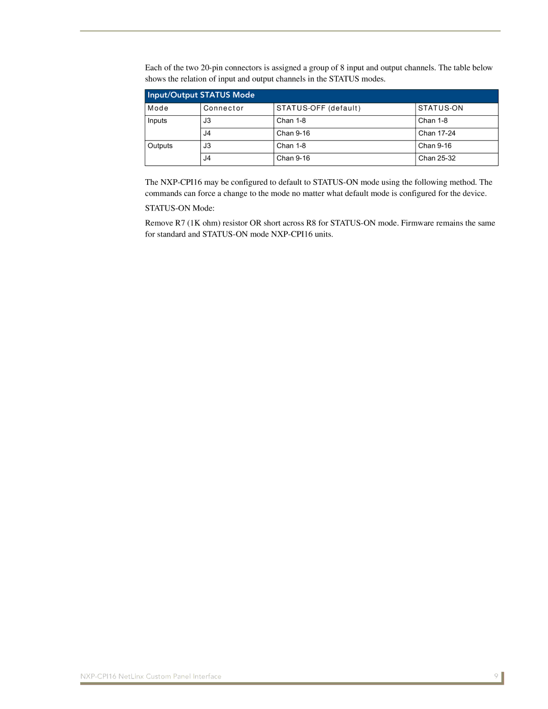
Each of the two 20-pin connectors is assigned a group of 8 input and output channels. The table below shows the relation of input and output channels in the STATUS modes.
Input/Output STATUS Mode
Mode | Connector | STATUS-OFF (default) | STATUS-ON |
| | | |
Inputs | J3 | Chan 1-8 | Chan 1-8 |
| | | |
| J4 | Chan 9-16 | Chan 17-24 |
| | | |
Outputs | J3 | Chan 1-8 | Chan 9-16 |
| | | |
| J4 | Chan 9-16 | Chan 25-32 |
| | | |
The NXP-CPI16 may be configured to default to STATUS-ON mode using the following method. The commands can force a change to the mode no matter what default mode is configured for the device.
STATUS-ON Mode:
Remove R7 (1K ohm) resistor OR short across R8 for STATUS-ON mode. Firmware remains the same for standard and STATUS-ON mode NXP-CPI16 units.
NXP-CPI16 NetLinx Custom Panel Interface | 9 |
| |