|
| |
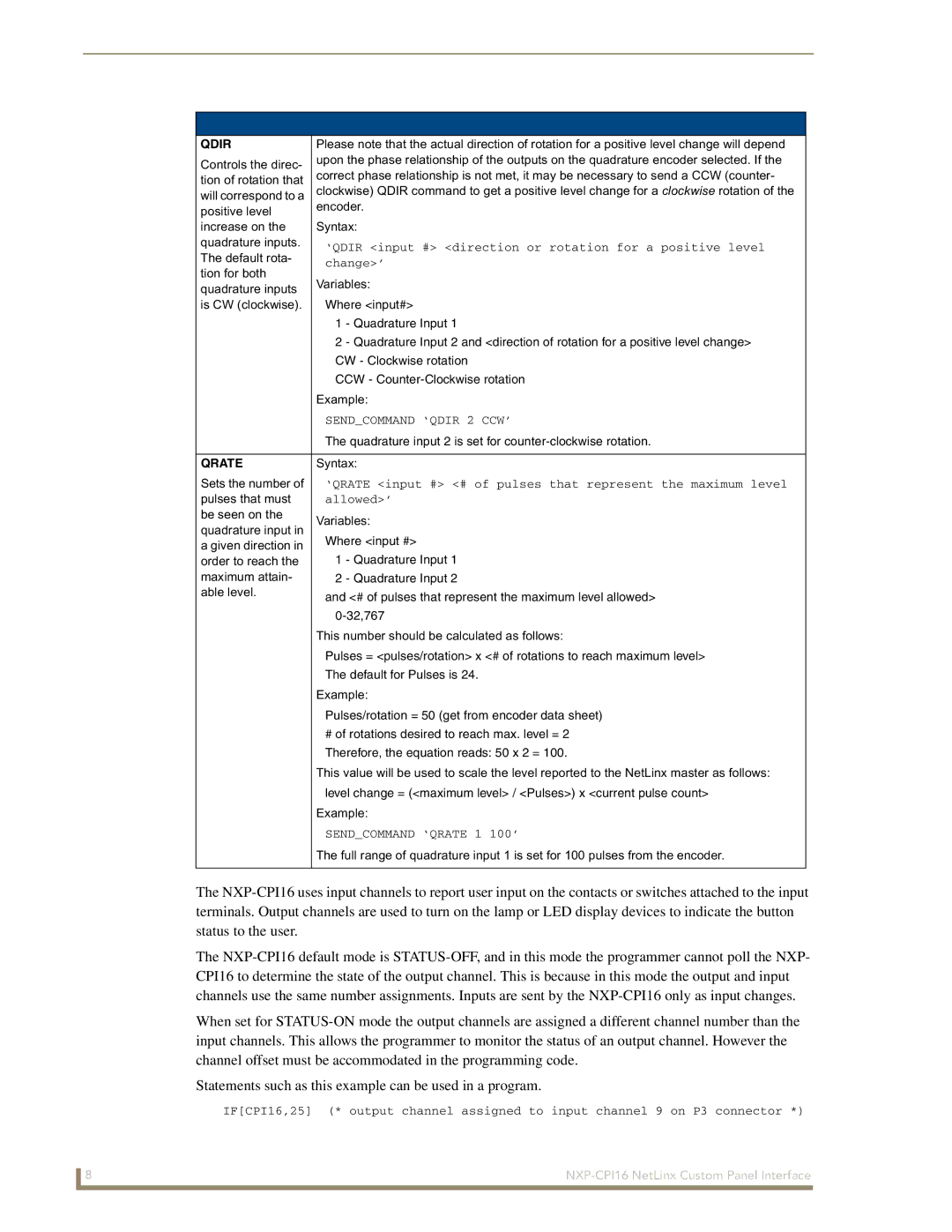
QDIR | Please note that the actual direction of rotation for a positive level change will depend | |
Controls the direc- | upon the phase relationship of the outputs on the quadrature encoder selected. If the | |
correct phase relationship is not met, it may be necessary to send a CCW (counter- | ||
tion of rotation that | ||
clockwise) QDIR command to get a positive level change for a clockwise rotation of the | ||
will correspond to a | ||
positive level | encoder. | |
| ||
increase on the | Syntax: | |
quadrature inputs. | ‘QDIR <input #> <direction or rotation for a positive level | |
The default rota- | ||
change>’ | ||
tion for both | ||
Variables: | ||
quadrature inputs | ||
| ||
is CW (clockwise). | Where <input#> | |
| 1 - Quadrature Input 1 | |
| 2 - Quadrature Input 2 and <direction of rotation for a positive level change> | |
| CW - Clockwise rotation | |
| CCW - | |
| Example: | |
| SEND_COMMAND ‘QDIR 2 CCW’ | |
| The quadrature input 2 is set for | |
|
| |
QRATE | Syntax: | |
Sets the number of | ‘QRATE <input #> <# of pulses that represent the maximum level | |
pulses that must | allowed>’ | |
be seen on the | Variables: | |
quadrature input in | ||
Where <input #> | ||
a given direction in | ||
1 - Quadrature Input 1 | ||
order to reach the | ||
maximum attain- | 2 - Quadrature Input 2 | |
able level. | and <# of pulses that represent the maximum level allowed> | |
| ||
| ||
| This number should be calculated as follows: | |
| Pulses = <pulses/rotation> x <# of rotations to reach maximum level> | |
| The default for Pulses is 24. | |
| Example: | |
| Pulses/rotation = 50 (get from encoder data sheet) | |
| # of rotations desired to reach max. level = 2 | |
| Therefore, the equation reads: 50 x 2 = 100. | |
| This value will be used to scale the level reported to the NetLinx master as follows: | |
| level change = (<maximum level> / <Pulses>) x <current pulse count> | |
| Example: | |
| SEND_COMMAND ‘QRATE 1 100’ | |
| The full range of quadrature input 1 is set for 100 pulses from the encoder. | |
|
|
The
The
When set for
Statements such as this example can be used in a program.
IF[CPI16,25] (* output channel assigned to input channel 9 on P3 connector *)
8 |