Input and Output Connectors
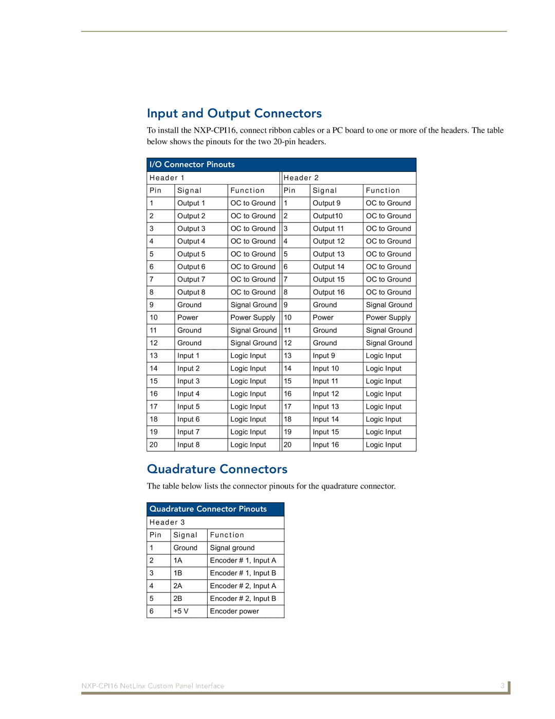
To install the
I/O Connector Pinouts
Header 1 |
|
| Header 2 |
| ||
|
|
|
|
|
|
|
Pin | Signal | Function |
| Pin | Signal | Function |
|
|
|
|
|
|
|
1 | Output 1 | OC to Ground |
| 1 | Output 9 | OC to Ground |
|
|
|
|
|
|
|
2 | Output 2 | OC to Ground |
| 2 | Output10 | OC to Ground |
|
|
|
|
|
|
|
3 | Output 3 | OC to Ground |
| 3 | Output 11 | OC to Ground |
|
|
|
|
|
|
|
4 | Output 4 | OC to Ground |
| 4 | Output 12 | OC to Ground |
|
|
|
|
|
|
|
5 | Output 5 | OC to Ground |
| 5 | Output 13 | OC to Ground |
|
|
|
|
|
|
|
6 | Output 6 | OC to Ground |
| 6 | Output 14 | OC to Ground |
|
|
|
|
|
|
|
7 | Output 7 | OC to Ground |
| 7 | Output 15 | OC to Ground |
|
|
|
|
|
|
|
8 | Output 8 | OC to Ground |
| 8 | Output 16 | OC to Ground |
|
|
|
|
|
|
|
9 | Ground | Signal Ground |
| 9 | Ground | Signal Ground |
|
|
|
|
|
|
|
10 | Power | Power Supply |
| 10 | Power | Power Supply |
|
|
|
|
|
|
|
11 | Ground | Signal Ground |
| 11 | Ground | Signal Ground |
|
|
|
|
|
|
|
12 | Ground | Signal Ground |
| 12 | Ground | Signal Ground |
|
|
|
|
|
|
|
13 | Input 1 | Logic Input |
| 13 | Input 9 | Logic Input |
|
|
|
|
|
|
|
14 | Input 2 | Logic Input |
| 14 | Input 10 | Logic Input |
|
|
|
|
|
|
|
15 | Input 3 | Logic Input |
| 15 | Input 11 | Logic Input |
|
|
|
|
|
|
|
16 | Input 4 | Logic Input |
| 16 | Input 12 | Logic Input |
|
|
|
|
|
|
|
17 | Input 5 | Logic Input |
| 17 | Input 13 | Logic Input |
|
|
|
|
|
|
|
18 | Input 6 | Logic Input |
| 18 | Input 14 | Logic Input |
|
|
|
|
|
|
|
19 | Input 7 | Logic Input |
| 19 | Input 15 | Logic Input |
|
|
|
|
|
|
|
20 | Input 8 | Logic Input |
| 20 | Input 16 | Logic Input |
|
|
|
|
|
|
|
Quadrature Connectors
The table below lists the connector pinouts for the quadrature connector.
Quadrature Connector Pinouts
Header 3
Pin | Signal | Function |
|
|
|
1 | Ground | Signal ground |
|
|
|
2 | 1A | Encoder # 1, Input A |
|
|
|
3 | 1B | Encoder # 1, Input B |
|
|
|
4 | 2A | Encoder # 2, Input A |
|
|
|
5 | 2B | Encoder # 2, Input B |
|
|
|
6 | +5 V | Encoder power |
|
|
|
3 | |
|
|