Hardware Specifications
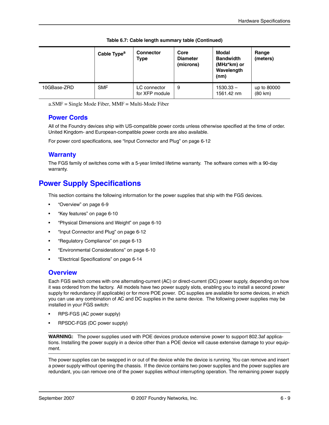
Table 6.7: Cable length summary table (Continued)
| Cable Typea | Connector | Core | Modal | Range |
|
| Type | Diameter | Bandwidth | (meters) |
|
|
| (microns) | (MHz*km) or |
|
|
|
|
| Wavelength |
|
|
|
|
| (nm) |
|
|
|
|
|
|
|
SMF | LC connector | 9 | 1530.33 – | up to 80000 | |
|
| for XFP module |
| 1561.42 nm | (80 km) |
|
|
|
|
|
|
a.SMF = Single Mode Fiber, MMF =
Power Cords
All of the Foundry devices ship with
For power cord specifications, see “Input Connector and Plug” on page
Warranty
The FGS family of switches come with a
Power Supply Specifications
This section contains the following information for the power supplies that ship with the FGS devices.
•“Overview” on page
•“Key features” on page
•“Physical Dimensions and Weight” on page
•“Input Connector and Plug” on page
•“Regulatory Compliance” on page
•“Environmental Considerations” on page
•“Electrical Specifications” on page
Overview
Each FGS switch comes with one
•
•
WARNING: The power supplies used with POE devices produce extensive power to support 802.3af applica- tions. Installing the power supply in a device other than a POE device will cause extensive damage to your equip- ment.
The power supplies can be swapped in or out of the device while the device is running. You can remove and insert a power supply without opening the chassis. If the device contains two power supplies and the power supplies are redundant, you can remove one of the power supplies without interrupting operation. The remaining power supply
September 2007 | © 2007 Foundry Networks, Inc. | 6 - 9 |