FastIron GS Compact Layer 2 Switch Hardware Installation Guide
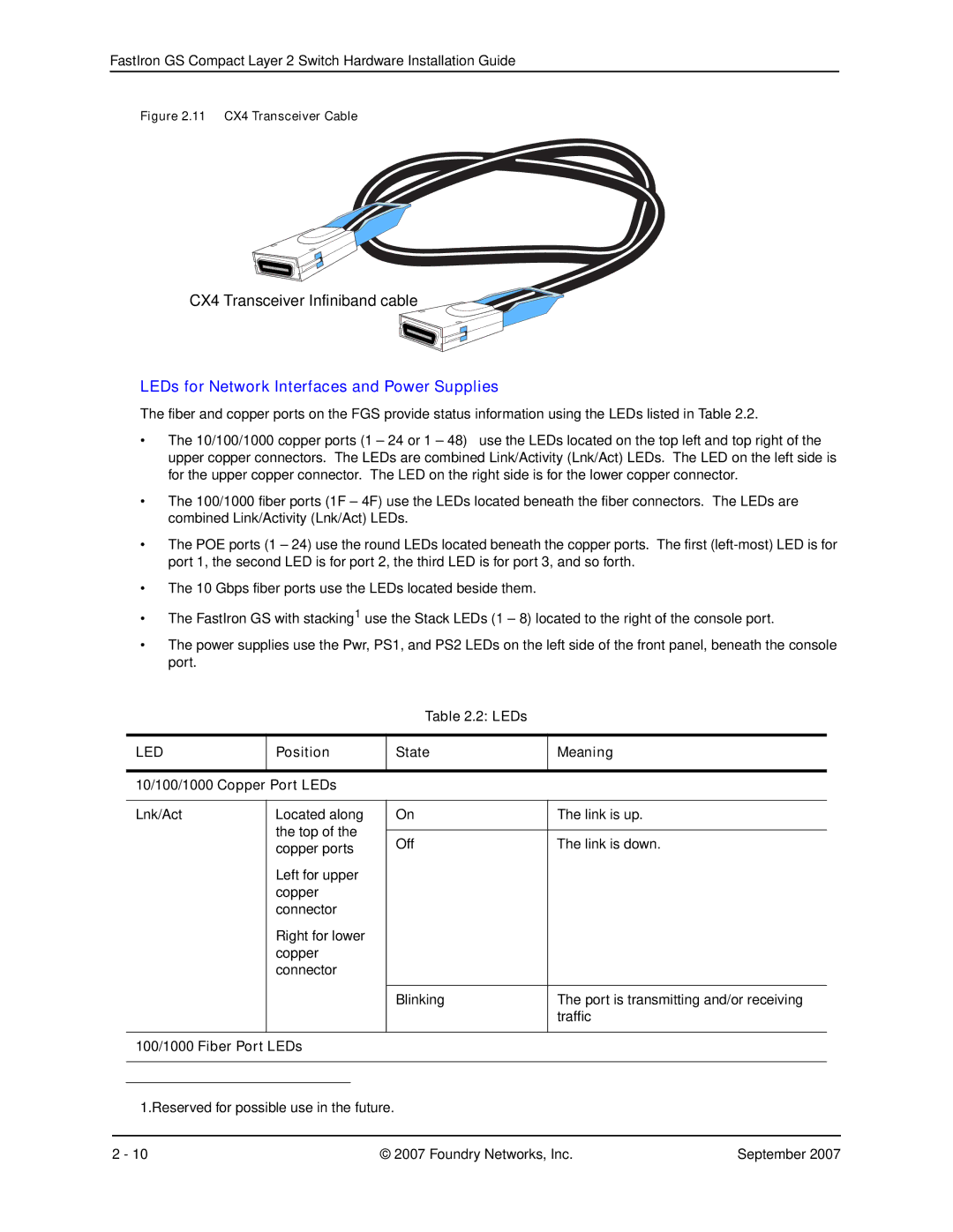
Figure 2.11 CX4 Transceiver Cable
CX4 Transceiver Infiniband cable
LEDs for Network Interfaces and Power Supplies
The fiber and copper ports on the FGS provide status information using the LEDs listed in Table 2.2.
•The 10/100/1000 copper ports (1 – 24 or 1 – 48) use the LEDs located on the top left and top right of the upper copper connectors. The LEDs are combined Link/Activity (Lnk/Act) LEDs. The LED on the left side is for the upper copper connector. The LED on the right side is for the lower copper connector.
•The 100/1000 fiber ports (1F – 4F) use the LEDs located beneath the fiber connectors. The LEDs are combined Link/Activity (Lnk/Act) LEDs.
•The POE ports (1 – 24) use the round LEDs located beneath the copper ports. The first
•The 10 Gbps fiber ports use the LEDs located beside them.
•The FastIron GS with stacking1 use the Stack LEDs (1 – 8) located to the right of the console port.
•The power supplies use the Pwr, PS1, and PS2 LEDs on the left side of the front panel, beneath the console port.
Table 2.2: LEDs
LED | Position | State | Meaning | |
|
|
|
|
|
10/100/1000 Copper Port LEDs |
|
| ||
|
|
|
|
|
Lnk/Act | Located along | On | The link is up. | |
| the top of the |
|
| |
| Off | The link is down. | ||
| copper ports | |||
|
|
| ||
| Left for upper |
|
| |
| copper |
|
| |
| connector |
|
| |
| Right for lower |
|
| |
| copper |
|
| |
| connector |
|
| |
|
|
|
|
|
|
|
| Blinking | The port is transmitting and/or receiving |
|
|
|
| traffic |
|
|
|
|
|
100/1000 Fiber Port LEDs |
|
| ||
|
|
|
|
|
|
|
|
|
|
1.Reserved for possible use in the future.
2 - 10 | © 2007 Foundry Networks, Inc. | September 2007 |