FastIron GS Compact Layer 2 Switch Hardware Installation Guide
Table 2.2: LEDs (Continued)
LED
Position
State
Meaning
Stacking LEDs
Reserved for future use
Fiber Optic Modules
Table 6.7 in the chapter “Hardware Specifications” lists the types of fiber optic modules (SFPs and XFPs) supported on Foundry’s FGS devices.
Table 2.1 lists the description that displays in the output of the show media command for each media type.
Power Supplies
Each FGS device comes with one
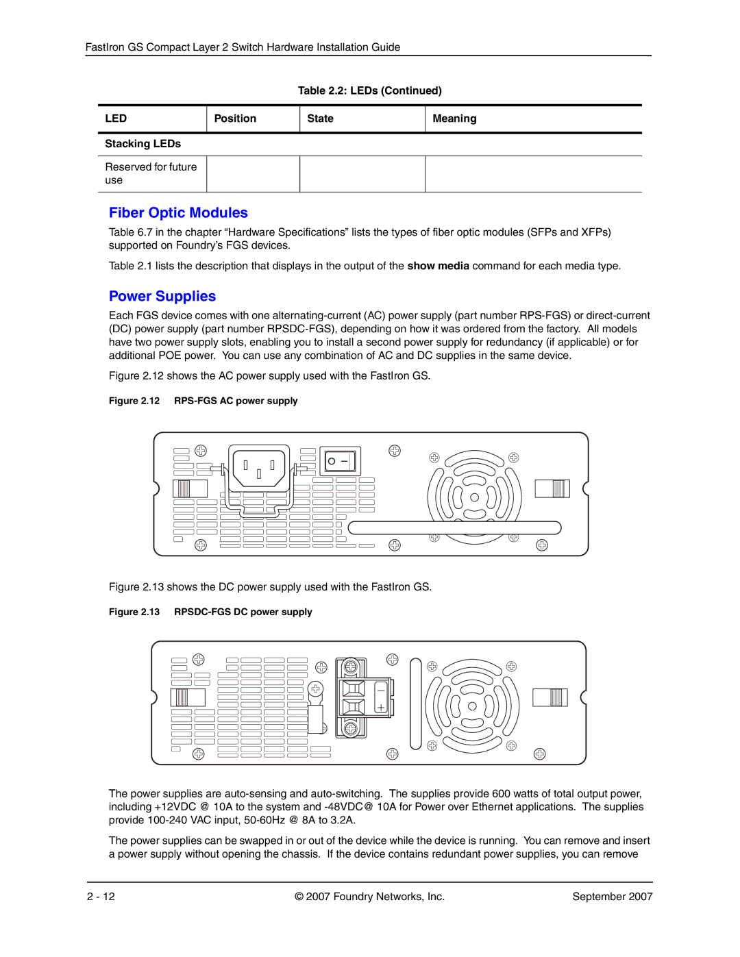
Figure 2.12 shows the AC power supply used with the FastIron GS.
Figure 2.12 RPS-FGS AC power supply
Figure 2.13 shows the DC power supply used with the FastIron GS.
Figure 2.13 RPSDC-FGS DC power supply
The power supplies are
The power supplies can be swapped in or out of the device while the device is running. You can remove and insert a power supply without opening the chassis. If the device contains redundant power supplies, you can remove
2 - 12 | © 2007 Foundry Networks, Inc. | September 2007 |
