FastIron GS Compact Layer 2 Switch Hardware Installation Guide
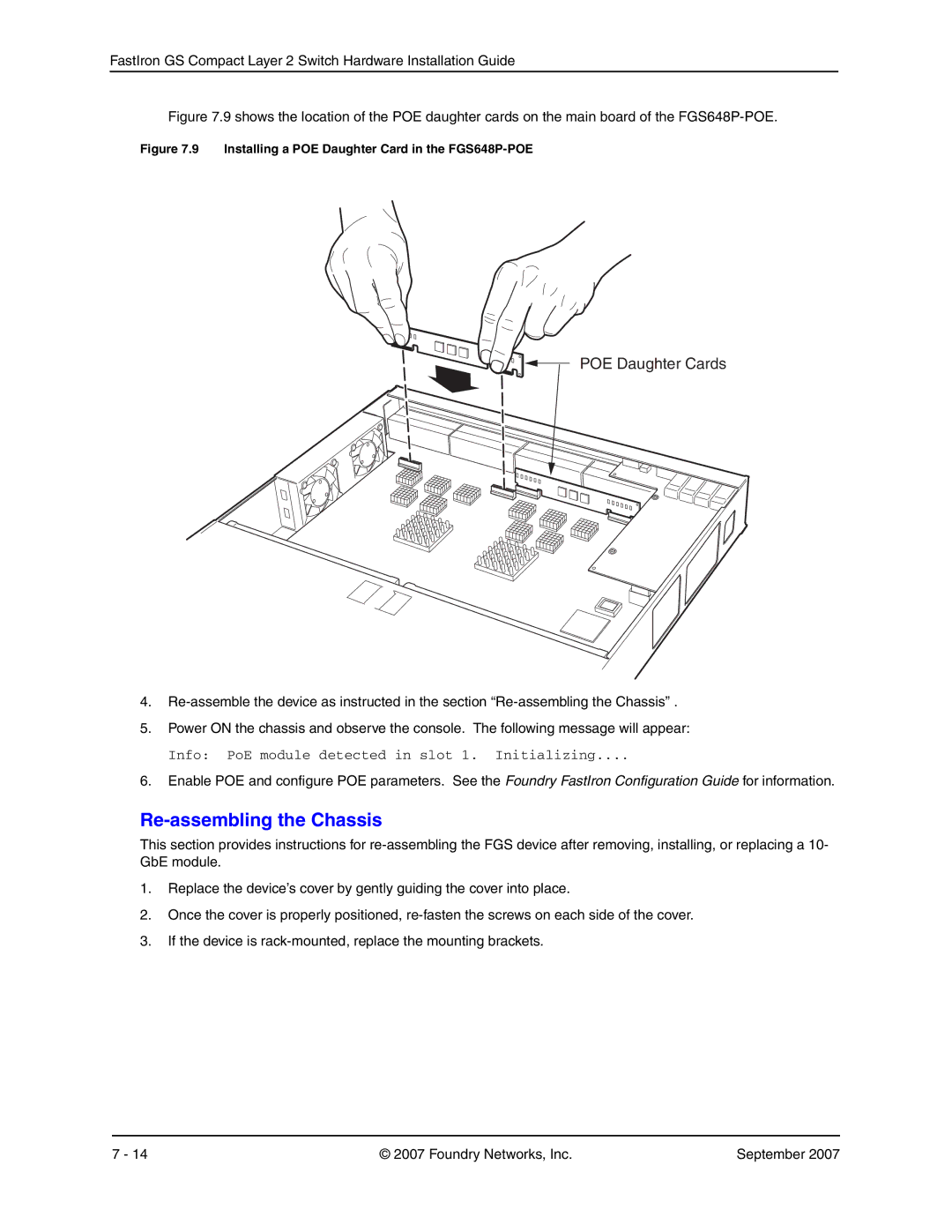
Figure 7.9 shows the location of the POE daughter cards on the main board of the FGS648P-POE.
Figure 7.9 Installing a POE Daughter Card in the FGS648P-POE
POE Daughter Cards
4.
5.Power ON the chassis and observe the console. The following message will appear:
Info: PoE module detected in slot 1. Initializing....
6.Enable POE and configure POE parameters. See the Foundry FastIron Configuration Guide for information.
Re-assembling the Chassis
This section provides instructions for
1.Replace the device’s cover by gently guiding the cover into place.
2.Once the cover is properly positioned,
3.If the device is
7 - 14 | © 2007 Foundry Networks, Inc. | September 2007 |