FastIron GS Compact Layer 2 Switch Hardware Installation Guide
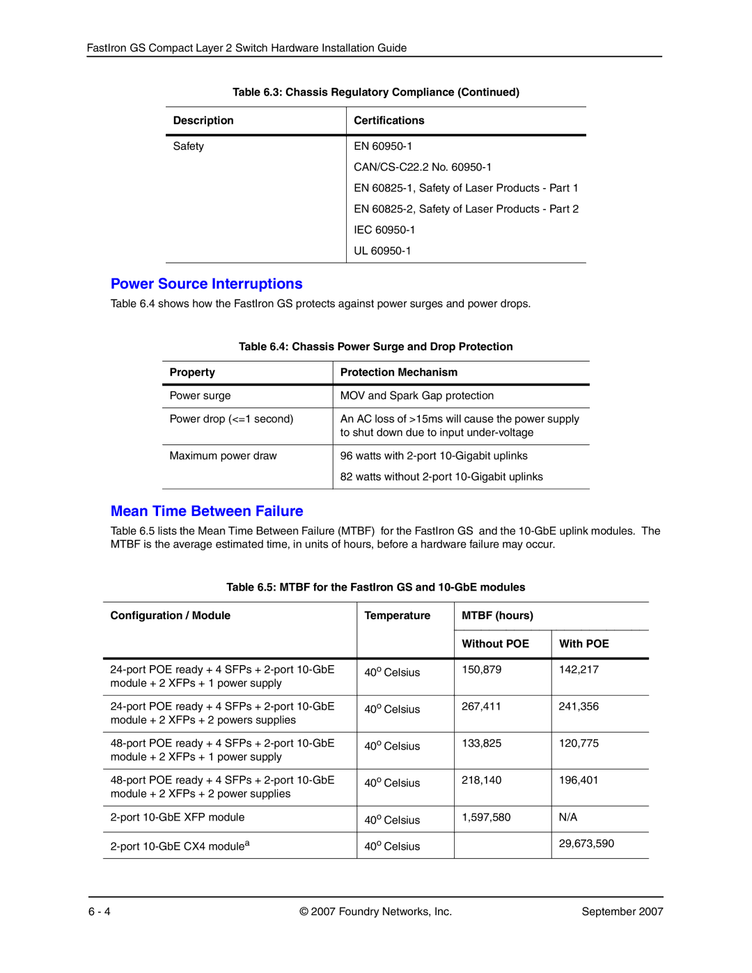
Table 6.3: Chassis Regulatory Compliance (Continued)
Description | Certifications |
|
|
Safety | EN |
| |
| EN |
| EN |
| IEC |
| UL |
|
|
Power Source Interruptions
Table 6.4 shows how the FastIron GS protects against power surges and power drops.
Table 6.4: Chassis Power Surge and Drop Protection
Property | Protection Mechanism |
|
|
Power surge | MOV and Spark Gap protection |
|
|
Power drop (<=1 second) | An AC loss of >15ms will cause the power supply |
| to shut down due to input |
|
|
Maximum power draw | 96 watts with |
| 82 watts without |
|
|
Mean Time Between Failure
Table 6.5 lists the Mean Time Between Failure (MTBF) for the FastIron GS and the
Table 6.5: MTBF for the FastIron GS and
Configuration / Module | Temperature | MTBF (hours) |
| |
|
|
|
|
|
|
|
| Without POE | With POE |
|
|
|
| |
40o Celsius | 150,879 | 142,217 | ||
module + 2 | XFPs + 1 power supply |
|
|
|
|
|
|
| |
40o Celsius | 267,411 | 241,356 | ||
module + 2 | XFPs + 2 powers supplies |
|
|
|
|
|
|
| |
40o Celsius | 133,825 | 120,775 | ||
module + 2 | XFPs + 1 power supply |
|
|
|
|
|
|
| |
40o Celsius | 218,140 | 196,401 | ||
module + 2 | XFPs + 2 power supplies |
|
|
|
|
|
|
| |
40o Celsius | 1,597,580 | N/A | ||
40o Celsius |
| 29,673,590 | ||
6 - 4 | © 2007 Foundry Networks, Inc. | September 2007 |