FastIron GS Compact Layer 2 Switch Hardware Installation Guide
NOTE: The handle on the front panel of the power supply may block access to the negative and positive terminal screws. You may need to temporarily remove the receptacle for the positive and negative terminals if you can’t access the screws used to hold the wires in the connectors. The figure below shows the screws that secure the receptacle to the power supply.
6.Connect the ground, positive and negative wires as follows:
•Slip the ground wire into the opening under the ![]() marking until the wire is fully in place, then use the crimper to crimp the lug snugly onto the wire. Gently pull the lug away from the wire to verify that the lug is securely fastened.
marking until the wire is fully in place, then use the crimper to crimp the lug snugly onto the wire. Gently pull the lug away from the wire to verify that the lug is securely fastened.
•Connect the
•Connect the 48 RTN lead to the positive (+) terminal and tighten the positive terminal screw.
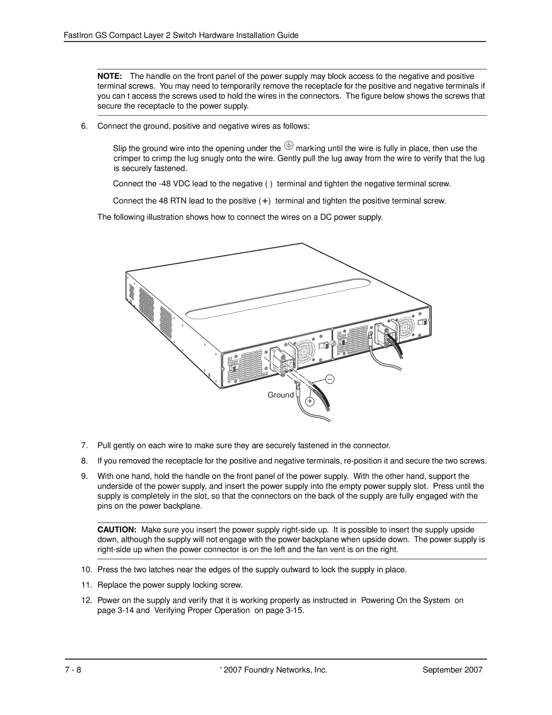
The following illustration shows how to connect the wires on a DC power supply.
–
Ground 
+
7.Pull gently on each wire to make sure they are securely fastened in the connector.
8.If you removed the receptacle for the positive and negative terminals,
9.With one hand, hold the handle on the front panel of the power supply. With the other hand, support the underside of the power supply, and insert the power supply into the empty power supply slot. Press until the supply is completely in the slot, so that the connectors on the back of the supply are fully engaged with the pins on the power backplane.
CAUTION: Make sure you insert the power supply
10.Press the two latches near the edges of the supply outward to lock the supply in place.
11.Replace the power supply locking screw.
12.Power on the supply and verify that it is working properly as instructed in “Powering On the System” on page
7 - 8 | © 2007 Foundry Networks, Inc. | September 2007 |