Hardware Specifications
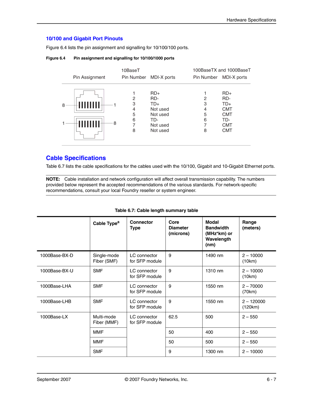
10/100 and Gigabit Port Pinouts
Figure 6.4 lists the pin assignment and signalling for 10/100/100 ports.
Figure 6.4 Pin assignment and signalling for 10/100/1000 ports
| 10BaseT | 100BaseTX and 1000BaseT |
Pin Assignment | Pin Number | Pin Number |
|
|
|
8
1
| 1 | RD+ | 1 | RD+ | |
| 2 | RD- | 2 | RD- | |
1 | 3 | TD+ | 3 | TD+ | |
| 4 | Not used | 4 | CMT | |
| 5 | Not used | 5 | CMT | |
8 | 6 | TD- | 6 | TD- | |
7 | Not used | 7 | CMT | ||
| |||||
| 8 | Not used | 8 | CMT |
Cable Specifications
Table 6.7 lists the cable specifications for the cables used with the 10/100, Gigabit and
NOTE: Cable installation and network configuration will affect overall transmission capability. The numbers provided below represent the accepted recommendations of the various standards. For
Table 6.7: Cable length summary table
| Cable Typea | Connector | Core | Modal | Range | |
|
| Type | Diameter | Bandwidth | (meters) | |
|
|
| (microns) | (MHz*km) or |
|
|
|
|
|
| Wavelength |
|
|
|
|
|
| (nm) |
|
|
|
|
|
|
|
|
|
LC connector | 9 | 1490 nm | 2 | – 10000 | ||
| Fiber (SMF) | for SFP module |
|
| (10km) | |
|
|
|
|
|
|
|
SMF | LC connector | 9 | 1310 nm | 2 | – 10000 | |
|
| for SFP module |
|
| (10km) | |
|
|
|
|
|
|
|
SMF | LC connector | 9 | 1550 nm | 2 | – 70000 | |
|
| for SFP module |
|
| (70km) | |
|
|
|
|
|
|
|
SMF | LC connector | 9 | 1550 nm | 2 | – 120000 | |
|
| for SFP module |
|
| (120km) | |
|
|
|
|
|
|
|
LC connector | 62.5 | 500 | 2 | – 550 | ||
| Fiber (MMF) | for SFP module |
|
|
|
|
|
|
|
|
|
|
|
| MMF |
| 50 | 400 | 2 | – 550 |
|
|
|
|
|
|
|
| MMF |
| 50 | 500 | 2 | – 550 |
|
|
|
|
|
|
|
| SMF |
| 9 | 1300 nm | 2 | – 10000 |
|
|
|
|
|
|
|
September 2007 | © 2007 Foundry Networks, Inc. | 6 - 7 |