FastIron GS Compact Layer 2 Switch Hardware Installation Guide
•A management station, such as a PC running a terminal emulation application.
•A
You use the serial connection to perform basic configuration tasks such as assigning an IP address and network mask to the system. This information is required for managing the system using the Web management interface or IronView Network Manager, or using the CLI through Telnet.
Summary of Installation Tasks
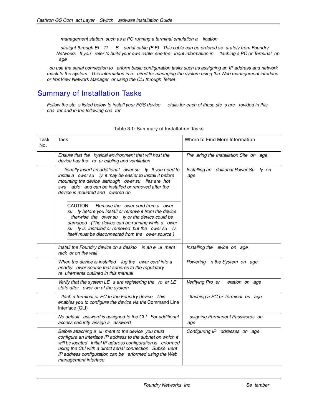
Follow the steps listed below to install your FGS device. Details for each of these steps are provided in this chapter and in the following chapter.
Table 3.1: Summary of Installation Tasks
Task | Task |
| Where to Find More Information | |
No. |
|
|
|
|
|
|
|
| |
1 | Ensure that the physical environment that will host the |
| “Preparing the Installation Site” on page | |
| device has the proper cabling and ventilation. |
|
| |
|
|
|
| |
2 | Optionally insert an additional power supply. If you need to |
| “Installing an Additional Power Supply” on | |
| install a power supply, it may be easier to install it before |
| page | |
| mounting the device, although power supplies are “hot |
|
| |
| swappable”, and can be installed or removed after the |
|
| |
| device is mounted and |
|
| |
|
|
|
|
|
|
| CAUTION: Remove the power cord from a power |
|
|
|
| supply before you install or remove it from the device. |
|
|
|
| Otherwise, the power supply or the device could be |
|
|
|
| damaged. (The device can be running while a power |
|
|
|
| supply is installed or removed, but the power supply |
|
|
|
| itself must be disconnected from the power source.) |
|
|
|
|
|
|
|
|
|
|
| |
4 | Install the Foundry device on a desktop, in an equipment |
| “Installing the Device” on page | |
| rack, or on the wall. |
|
| |
|
|
|
| |
5 | When the device is installed, plug the power cord into a |
| “Powering On the System” on page | |
| nearby power source that adheres to the regulatory |
|
| |
| requirements outlined in this manual. |
|
| |
|
|
|
| |
6 | Verify that the system LEDs are registering the proper LED |
| “Verifying Proper Operation” on page | |
| state after |
|
| |
|
|
|
| |
7 | Attach a terminal or PC to the Foundry device. This |
| “Attaching a PC or Terminal” on page | |
| enables you to configure the device via the Command Line |
|
| |
| Interface (CLI). |
|
| |
|
|
|
| |
8 | No default password is assigned to the CLI. For additional |
| “Assigning Permanent Passwords” on | |
| access security, assign a password. |
| page | |
|
|
|
| |
9 | Before attaching equipment to the device, you must |
| “Configuring IP Addresses” on page | |
| configure an interface IP address to the subnet on which it |
|
| |
| will be located. Initial IP address configuration is performed |
|
| |
| using the CLI with a direct serial connection. Subsequent |
|
| |
| IP address configuration can be performed using the Web |
|
| |
| management interface. |
|
| |
|
|
|
|
|
3 - 2 | © 2007 Foundry Networks, Inc. | September 2007 |