FastIron GS Compact Layer 2 Switch Hardware Installation Guide
Observing the Power Status LEDs
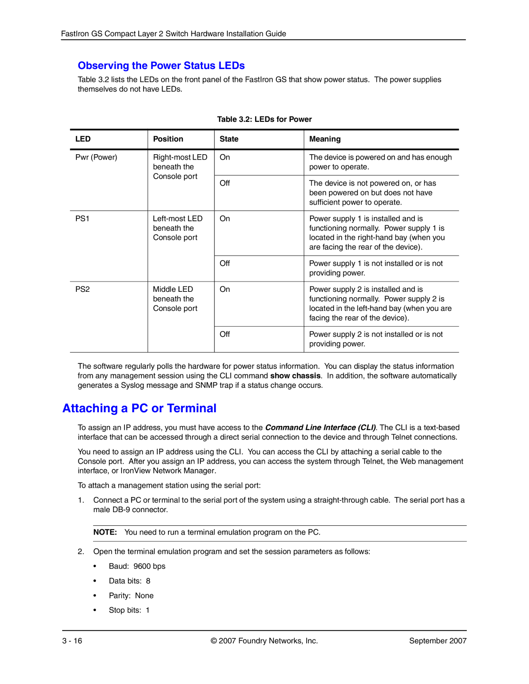
Table 3.2 lists the LEDs on the front panel of the FastIron GS that show power status. The power supplies themselves do not have LEDs.
Table 3.2: LEDs for Power
LED | Position | State | Meaning |
|
|
|
|
Pwr (Power) | On | The device is powered on and has enough | |
| beneath the |
| power to operate. |
| Console port |
|
|
| Off | The device is not powered on, or has | |
|
| ||
|
|
| been powered on but does not have |
|
|
| sufficient power to operate. |
|
|
|
|
PS1 | On | Power supply 1 is installed and is | |
| beneath the |
| functioning normally. Power supply 1 is |
| Console port |
| located in the |
|
|
| are facing the rear of the device). |
|
|
|
|
|
| Off | Power supply 1 is not installed or is not |
|
|
| providing power. |
|
|
|
|
PS2 | Middle LED | On | Power supply 2 is installed and is |
| beneath the |
| functioning normally. Power supply 2 is |
| Console port |
| located in the |
|
|
| facing the rear of the device). |
|
|
|
|
|
| Off | Power supply 2 is not installed or is not |
|
|
| providing power. |
|
|
|
|
The software regularly polls the hardware for power status information. You can display the status information from any management session using the CLI command show chassis. In addition, the software automatically generates a Syslog message and SNMP trap if a status change occurs.
Attaching a PC or Terminal
To assign an IP address, you must have access to the Command Line Interface (CLI). The CLI is a
You need to assign an IP address using the CLI. You can access the CLI by attaching a serial cable to the Console port. After you assign an IP address, you can access the system through Telnet, the Web management interface, or IronView Network Manager.
To attach a management station using the serial port:
1.Connect a PC or terminal to the serial port of the system using a
NOTE: You need to run a terminal emulation program on the PC.
2.Open the terminal emulation program and set the session parameters as follows:
•Baud: 9600 bps
•Data bits: 8
•Parity: None
•Stop bits: 1
3 - 16 | © 2007 Foundry Networks, Inc. | September 2007 |
