FastIron GS Compact Layer 2 Switch Hardware Installation Guide
Installing a DC Power Supply
Use the following procedures for installing DC power supplies in the FastIron GS. The following illustration shows the front panel of a DC power supply.
WARNING: Before beginning the installation, see the precautions in “Power Supply Precautions” on page
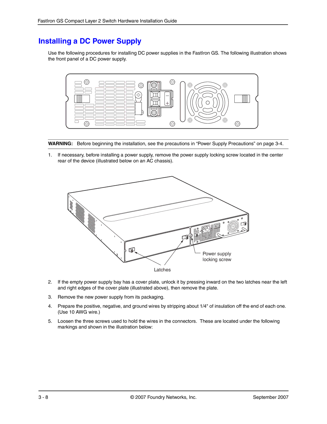
1.If necessary, before installing a power supply, remove the power supply locking screw located in the center rear of the device (illustrated below on an AC chassis).
Power supply locking screw
Latches
2.If the empty power supply bay has a cover plate, unlock it by pressing inward on the two latches near the left and right edges of the cover plate (illustrated above), then remove the plate.
3.Remove the new power supply from its packaging.
4.Prepare the positive, negative, and ground wires by stripping about 1/4" of insulation off the end of each one. (Use 10 AWG wire.)
5.Loosen the three screws used to hold the wires in the connectors. These are located under the following markings and shown in the illustration below:
3 - 8 | © 2007 Foundry Networks, Inc. | September 2007 |