STANDARD NOTES FOR SERVICING
Circuit Board Indications
1.The output pin of the 3 pin Regulator ICs is indicated as shown.
Top View | Bottom View |
Out | Input |
In |
2.For other ICs, pin 1 and every fifth pin are indicated as shown.
5
Pin 1 ![]()
![]()
![]()
![]()
![]()
![]()
![]()
10
3.The 1st pin of every male connector is indicated as shown.
Pin 1 ![]()
![]()
Instructions for Connectors
1.When you connect or disconnect the FFC (Flexible Foil Connector) cable, be sure to first disconnect the AC cord.
2.FFC (Flexible Foil Connector) cable should be inserted parallel into the connector, not at an angle.
FFC Cable
Connector
CBA
* Be careful to avoid a short circuit.
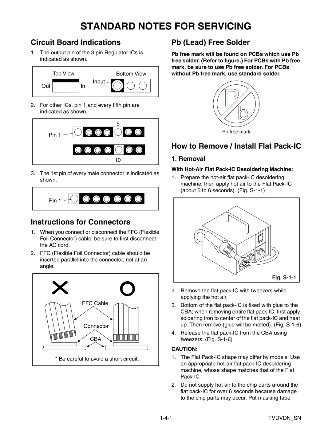
Pb (Lead) Free Solder
Pb free mark will be found on PCBs which use Pb free solder. (Refer to figure.) For PCBs with Pb free mark, be sure to use Pb free solder. For PCBs without Pb free mark, use standard solder.
Pb free mark
How to Remove / Install Flat Pack-IC
1. Removal
With Hot-Air Flat Pack-IC Desoldering Machine:
1.Prepare the
Fig. S-1-1
2.Remove the flat
3.Bottom of the flat
4.Release the flat
CAUTION:
1.The Flat
2.Do not supply hot air to the chip parts around the flat
TVDVDN_SN |