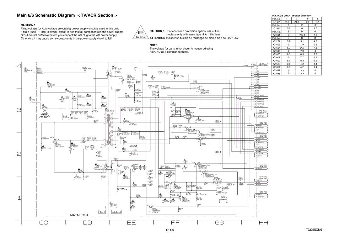
Main 6/6 Schematic Diagram < TV/VCR Section >
CAUTION ! |
|
|
|
|
|
|
|
| |
Fixed voltage (or Auto voltage selectable) power supply circuit is used in this unit. |
|
|
|
|
|
|
| CAUTION ! : For continued protection against risk of fire, | |
If Main Fuse (F1601) is blown , check to see that all components in the power supply |
|
|
|
|
|
|
| ||
|
|
|
|
|
|
| |||
|
|
|
|
|
|
| replace only with same type 4 A, 125V fuse. | ||
circuit are not defective before you connect the AC plug to the AC power supply. |
|
|
|
|
|
|
| ||
4A 125V | |||||||||
Otherwise it may cause some components in the power supply circuit to fail. | ATTENTION : Utiliser un fusible de rechange de même type de 4A, 125V. | ||||||||
|
|
|
|
|
|
| |||
NOTE:
The voltage for parts in hot circuit is measured using hot GND as a common terminal.
VOLTAGE CHART (Power off mode)
Ref. No. | 1 | 2 |
| 3 |
| 4 | |
IC1601 | 25.7 | 24.7 |
| 0.3 | 1.2 | ||
Ref. No. | 1 |
|
| 2 |
| 3 | |
IC1682 | 3.2 |
|
| 0 |
| 1.7 | |
Ref. No. | S |
|
| D |
| G | |
Q1601 | 0 |
|
| 162.8 |
| 1.9 | |
Ref. No. | E |
|
| C |
| B | |
Q1221 | 5.2 |
|
| 5.1 |
| 4.6 | |
Q1602 | 0 |
|
| 1.9 |
| 0.3 | |
Q1604 | 6.7 |
|
| 24.7 |
| 7.3 | |
Q1605 | 0 |
|
| 7.9 |
| 0 | |
Q1606 | 8.5 |
|
| 8.5 |
| 7.8 | |
Q1607 | 0 |
|
| 7.7 |
| 6.6 | |
Q1609 | 5.9 |
|
| 8.2 |
| 6.5 | |
Q1613 | 0.8 |
|
| 4.2 |
| 1.4 | |
Q1614 | 0.9 |
|
| 4.2 |
| 1.4 | |
Q1681 | 0 |
|
| 3.3 |
| 0 | |
Q1688 | 0 |
|
| 3.3 |
| 0 | |
T2202SCM6 |