Maintenance and Service Guide
Page
Contents
Removal and Replacement Preliminaries
Screw Listing Index
Product Description
Key
Models
Key Description Options
RAM
HP Pavilion zd7000 Series Notebook PC
DP353E ABF
DV601U ABA
DY624E ABU
PB950EA ABU
DP791A ABA
DP770E ABD
DS490U ABA
DR340U ABL
HP Compaq nx9500 Series Business Notebook Models
Features
Product Description
Product Description
Power Management
Clearing a Password
External Components
Component Function
Front and Right Side Components
Rear Panel and Left-Side Components
Parallel port
Keyboard Components
Component Function Fn key
Keyboard Components
Top Components
Turns the wireless network device on and off
Bottom Components
Bottom Components
Design Overview
Troubleshooting
Computer Setup and Diagnostics Utilities
Using Computer Setup
Select To Do This
File Menu
Security Menu
Selecting from the Security Menu
Security Menu
Advanced Menu
Selecting from the Advanced Menu
Drives in the system that support the test features
Obtaining, Saving or Printing Configuration Information
Using Diagnostics for Windows
Obtaining, Saving or Printing Diagnostic Test Information
Troubleshooting
Troubleshooting Flowcharts Overview
Troubleshooting Flowcharts
Flowchart No Power Part
Flowchart 2.1-Initial Troubleshooting
Flowchart 2.2-No Power, Part
Flowchart 2.3-No Power, Part
External
Flowchart 2.4-No Power, Part
Flowchart 2.5-No Power, Part
Flowchart 2.6-No Video, Part
Flowchart No Video Part
Flowchart 2.7-No Video, Part
Nonfunctioning expansion base
Flowchart 2.8-Nonfunctioning Expansion Base if applicable
Go to Flowchart 2.13-No OS Loading Diskette Drive
Flowchart 2.9-No Operating System OS Loading
Loading, Hard
Flowchart 2.10-No OS Loading, Hard Drive, Part
Flowchart No OS Loading, Hard Drive, Part
Flowchart 2.11-No OS Loading, Hard Drive, Part
Can bad sectors be fixed?
Flowchart 2.12-No OS Loading, Hard Drive, Part
Flowchart 2.13-No OS Loading, Diskette Drive
Flowchart 2.14-No OS Loading, CD-ROM or DVD-ROM Drive
Flowchart 2.15-No Audio, Part
Flowchart 2.16-No Audio, Part
Cmos
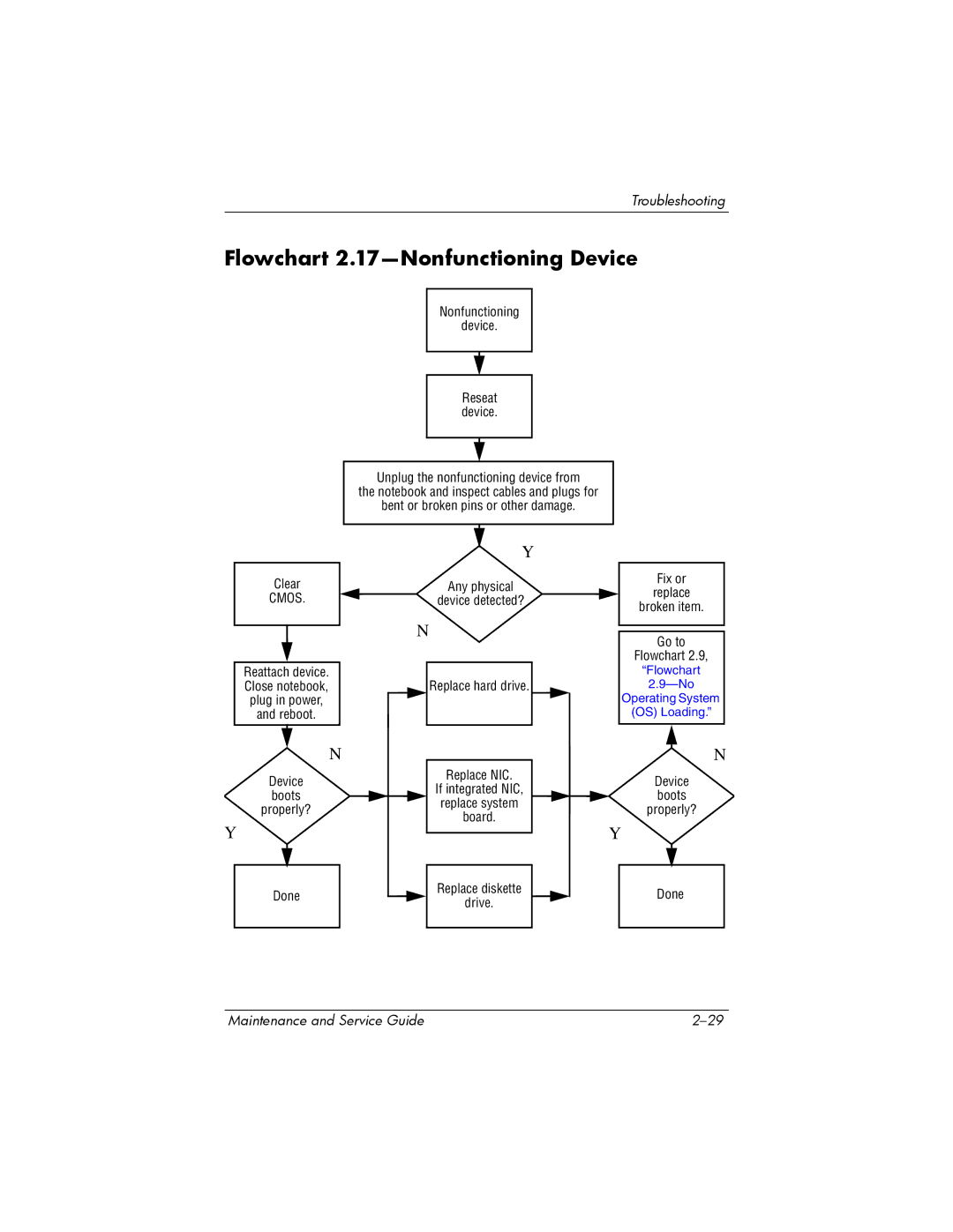
Flowchart 2.17-Nonfunctioning Device
Flowchart 2.18-Nonfunctioning Keyboard
Pointing device Not operating Properly Connect notebook
Flowchart 2.19-Nonfunctioning Pointing Device
Flowchart 2.20-No Network/Modem Connection
Illustrated Parts Catalog
Serial Number Location
Serial Number Location
Illustrated Parts Catalog Maintenance and Service Guide
Item Description Number Display assemblies
Spare Parts Notebook Major Components
Miscellaneous Plastics Kit
Illustrated Parts Catalog Maintenance and Service Guide
Top cover
Item Description Number Keyboards
Illustrated Parts Catalog Maintenance and Service Guide
Thermal Paste Kit not illustrated
Item Description Number
Illustrated Parts Catalog Maintenance and Service Guide
Description Number
Spare Part
Illustrated Parts Catalog Maintenance and Service Guide
Mini PCI communications cards
Memory modules, 333-MHz
Illustrated Parts Catalog Maintenance and Service Guide
Optical drives
Item Description Number Hard drives
Illustrated Parts Catalog Maintenance and Service Guide
Thermal Paste Fixture not illustrated
Spare Part Number 344852-001 or
Miscellaneous Plastics Kit Components
Miscellaneous Cable Kit Components Spare Part Number
Miscellaneous Cable Kit Components
Item Description
Mass Storage Devices Spare Part Number Information
Mass Storage Devices
USB v.1.1 diskette drive not illustrated
Personal Video Recorder cable kit
Personal Video Recorder Devices
Personal Video Recorder Devices
Miscellaneous
Watt AC adapter with power cord
Spare Parts Miscellaneous not illustrated
Description Number Logo Kit
Entertainment cable and Y-cable
Thermal paste fixture tool
Tools Required
Removal and Replacement Preliminaries
Plastic Parts
Service Considerations
Preventing Damage to Removable Drives
Preventing Electrostatic Damage
Packaging and Transporting Precautions
Grounding Equipment and Methods
Workstation Precautions
Relative Humidity Event 10% 40% 55%
Typical Electrostatic Voltage Levels
Material Use Voltage Protection Level
Static-Shielding Materials
Removal and Replacement Procedures
Serial Number
Disassembly Sequence Chart
Disassembly Sequence Chart
Section Description
Preparing the Notebook for Disassembly
Reverse the above procedure to install the battery pack
Hard drives
Removing the Hard Drive Cover
Reverse the above procedure to install the hard drive
» Attach the feet to the base enclosure as illustrated below
Memory Module
Removing the Memory Module/Mini PCI Compartment Cover
Reverse the above procedure to install a memory module
Mini PCI Communications Card
Removing a Mini PCI Communications Card
Optical Drive
Reverse the above procedure to install an optical drive
Keyboard
Removing the Fan Cover
Removing the Keyboard Screws
Releasing the Keyboard
Reverse the above procedure to install the keyboard
Keyboard Cover
Reverse the above procedure to install the keyboard cover
Display Assembly
Reverse the above procedure to install the display assembly
Top Cover
Removing the Top Cover Screws
Removing the Top Cover Screws
Reverse the above procedure to install the top cover
System Board
Removal and Replacement Procedures
Removing the System Board Screws and Standoffs
Reverse the above procedure to install the system board
RTC Battery
Heat Sink
Removing the Heat Sink
Reverse the above procedure to install the heat sink
Reverse the above procedure to install the fans
Processor
Reverse the above procedure to install the processor
SD Card Slot/Infrared Module
Removing the SD Card Slot/Infrared Module
Speakers
Reverse the above procedure to install the speakers
Stand-alone power requirements
Dimensions
Temperature
Maximum altitude unpressurized
Relative humidity noncondensing
Shock
Random Vibration
Inch, Wide SXGA+, TFT Display
Refresh rate
Inch Color TFT Wide XGA + Wide Viewing Angle TFT Display
Inch, Wide XGA+, TFT Display
Rpm Hard Drives
Operating
Disk rotational speed
Power supply output
Power supply input
External 120W AC Adapter
135W AC Adapter PFC
Connector
Input
Output
Energy
Cell Li-Ion Battery Pack
Run time
Recharge time
Laptop/Portable
Never
DVD/CD-RW Combo Drive
CD-DA, CD+EG, CD-MIDI, CD-TEXT
DVD+RW/R and CD-RW Combo Drive
8X MAX DVD-ROM Drive
Hardware DMA System Function
System DMA
Hardware IRQ System Function
System Interrupts
Address hex
System I/O Addresses
16F Unused
VGA
Size Memory Address System Function
System Memory Map
Table A-1 RJ-45 Network Jack
Pin Signal
Table A-3 Universal Serial Bus Port
Table A-2 RJ-11 Modem Jack
Table A-5 External Monitor Port
Table A-4 Video Jack
Table A-6 Audio-Out Headphone Jack
Pin Signal Audio-out Ground
Table A-7 Audio-In Microphone Jack
Pin Signal Audio-in Ground
Table A-8 Parallel Port
General Requirements
Conductor Power Cord Set
Country-Specific Requirements
Conductor Power Cord Set Requirements
Country Accredited Agency Applicable Note Number
BSI
Screw Listing
Table C-1 Phillips PM2.5×4.0 Screw
Color Qty Length Thread Width Black Where used
Head
Table C-1 Phillips PM2.5×4.0 Screw
Table C-2 Phillips PM2.5×5.0 Screw
Table C-2 Phillips PM2.5×5.0 Screw
Table C-3 Phillips PM2.5×6.0 Screw
Color Qty Length Thread Width Black 0mm Where used
Table C-4 Phillips PM2.5×8.0 Screw
Table C-4 Phillips PM2.5×8.0 Screw
Table C-4 Phillips PM2.5×8.0 Screw
Phillips M2.5×8.0 Screw Location
Table C-4 Phillips PM2.5×8.0 Screw
Table C-4 Phillips PM2.5×8.0 Screw
Head Color Qty. Length Thread Width
Table C-5 Slotted M1.5×10.0 Shoulder Screw
Table C-6 HM5.0×9.0 Standoff
Color Qty Length Thread Width Silver Where used
Table C-7 PM1.5×12.0 Spring-Loaded Shoulder Screw
Color Qty Length Thread Width Silver 12.0 mm Where used
Table C-8 Phillips PM1.5×4.0 Screw
Index
Index
Index-3
Index-4
Index-5
Index-6
Index
Index-8