Removal and Replacement Procedures
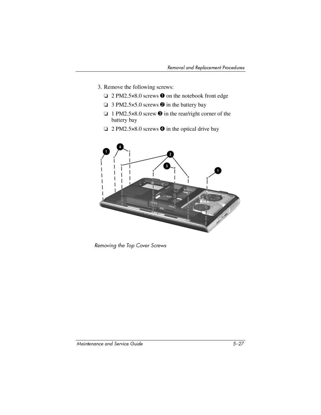
3.Remove the following screws:
❏2 PM2.5×8.0 screws 1 on the notebook front edge
❏3 PM2.5×5.0 screws 2 in the battery bay
❏1 PM2.5×8.0 screw 3 in the rear/right corner of the battery bay
❏2 PM2.5×8.0 screws 4 in the optical drive bay
Removing the Top Cover Screws
Maintenance and Service Guide |
