7. White Balance Adjustment
Purpose: To mix red, green and blue beams correctly for pure white.
Symptom of Misadjustment: White becomes bluish or reddish.
| Test Point | Adj. Point | Mode | Input |
|
|
|
|
|
|
|
|
|
|
| Screen | [CH. o / p] | RF | White Raster |
| buttons | (APL 100%) | ||
|
|
| ||
|
|
|
|
|
| Tape | M. EQ. |
| Spec. |
|
|
|
|
|
|
|
|
|
|
|
| Pattern |
|
|
Generator, | See below | |||
|
| Color analyzer |
|
|
|
|
|
|
|
|
| Figure |
|
|
Color Analyzer
Fig. 3
Note: Use service remote control unit
1.Operate the unit more than 20 minutes.
2.Face the unit to the east. Degauss the CRT using a degaussing coil.
3.Input the White Raster (APL 100%).
4.Set the color analyzer to the CHROMA mode and after zero point calibration, bring the optical receptor to the center on the tube surface (CRT).
5.Enter the Service mode. Press [VOL p] button on the service remote control unit and select “C/D” mode. (Display changes “C/D”, “7F” and Initial Setting cyclically when [VOL p] button is pressed.)
6.Press [4] button on the service remote control unit for Red adjustment. Press [5] button on the service remote control unit for Blue adjustment.
7.In each color mode, press [CH. o / p] buttons to adjust the values of color.
8.Adjust Red and Blue color so that the temperature becomes 9200K (x: 286 / y: 294) ±3%.
9.At this time,
10.Turn off and on again to return to normal mode. Receive APL 100% white signal and confirm that Chroma temperatures become 9200K (x: 286 / y: 294) ±3%.
Note: Confirm that Cut Off Adj. is correct after this adjustment, and attempt Cut Off Adj. if needed.
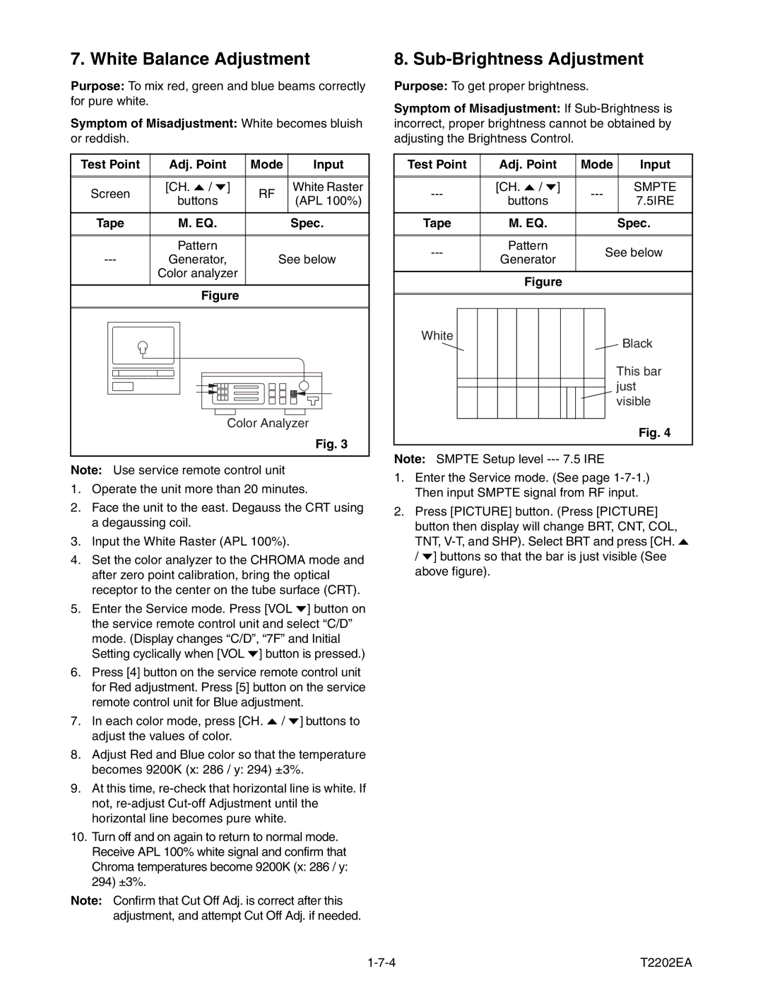
8. Sub-Brightness Adjustment
Purpose: To get proper brightness.
Symptom of Misadjustment: If
Test Point | Adj. Point | Mode | Input | ||
|
|
|
|
| |
|
|
|
|
| |
[CH. o / p] | SMPTE | ||||
buttons | 7.5IRE | ||||
|
| ||||
|
|
|
|
| |
Tape | M. EQ. |
| Spec. | ||
|
|
|
|
| |
|
|
|
|
| |
Pattern | See below | ||||
Generator | |||||
|
|
|
| ||
|
|
|
|
| |
| Figure |
|
|
| |
White | Black |
| |
| This bar |
| just |
| visible |
| Fig. 4 |
Note: SMPTE Setup level
1.Enter the Service mode. (See page
2.Press [PICTURE] button. (Press [PICTURE] button then display will change BRT, CNT, COL, TNT,
T2202EA |