CAUTION ! |
|
|
|
|
|
|
|
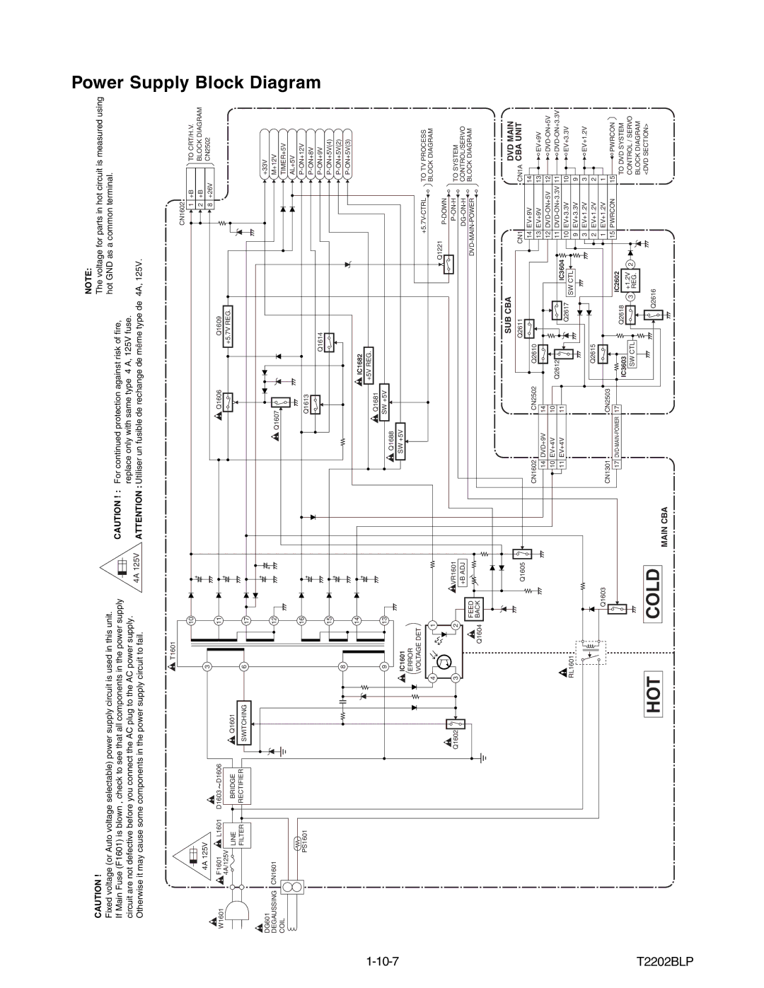
| NOTE: |
|
|
|
|
|
|
|
| The voltage for parts in hot circuit is measured using | |
Fixed voltage (or Auto voltage selectable) power supply circuit is used in this unit. |
|
|
|
|
|
|
|
| hot GND as a common terminal. |
If Main Fuse (F1601) is blown , check to see that all components in the power supply |
|
|
|
|
|
|
|
| CAUTION ! : For continued protection against risk of fire, |
circuit are not defective before you connect the AC plug to the AC power supply. |
|
|
|
|
|
|
|
| replace only with same type 4 A, 125V fuse. |
Otherwise it may cause some components in the power supply circuit to fail. | 4A 125V ATTENTION : Utiliser un fusible de rechange de même type de 4A, 125V. | ||||||||
|
|
|
|
|
| T1601 |
|
|
|
|
|
|
|
|
|
|
|
|
|
|
|
|
|
|
|
|
|
|
|
|
|
|
|
|
|
|
| CN1602 |
|
|
|
|
|
|
|
|
|
|
| 10 |
|
|
|
|
|
|
|
| 1 | +B |
| TO CRT/H.V. |
| 4A 125V |
|
|
| 3 |
|
|
|
|
|
|
|
|
|
| 2 | +B |
| BLOCK DIAGRAM | |
|
|
|
|
|
|
|
|
|
|
|
|
|
| 8 | +26V | CN2502 | ||||
|
|
|
|
|
|
|
|
|
|
|
|
|
|
|
| |||||
|
|
|
|
|
|
|
|
|
|
|
|
|
|
|
|
|
| |||
W1601 | F1601 | L1601 | D1603 | D1606 |
|
|
| 11 |
|
| Q1606 |
|
| Q1609 |
|
|
|
|
|
|
4A/125V |
|
|
|
|
|
|
|
|
|
| +5.7V REG. |
|
|
|
|
|
| |||
| BRIDGE | Q1601 |
|
|
|
|
|
|
|
|
|
|
|
|
| |||||
|
| LINE |
|
|
|
|
|
|
|
|
|
|
|
|
| |||||
|
|
|
|
|
|
|
|
|
|
|
|
|
|
|
|
| ||||
|
| FILTER | RECTIFIER | SWITCHING | 6 |
| 17 |
|
|
|
|
|
|
|
|
|
|
|
| |
|
|
|
|
|
|
|
|
|
|
|
|
|
|
|
|
|
| |||
|
|
|
|
|
|
|
|
|
|
|
|
|
|
|
|
|
|
|
| |
DG601 |
|
|
|
|
|
|
|
|
|
|
|
|
|
|
|
|
|
|
| +33V |
CN1601 |
|
|
|
|
|
|
|
|
|
|
|
|
|
|
|
|
|
|
| |
DEGAUSSING |
|
|
|
|
|
| 12 |
| Q1607 |
|
|
|
|
|
|
|
| M+12V | ||
COIL |
|
|
|
|
|
|
|
|
|
|
|
|
|
|
|
|
| TIMER+5V | ||
|
|
|
|
|
|
|
|
|
|
|
|
|
|
|
|
|
|
| ||
|
|
|
|
|
|
|
|
|
|
|
|
|
|
|
|
|
|
|
| AL+5V |
|
| PS1601 |
|
|
|
|
| 16 |
|
| Q1613 |
|
|
|
|
|
|
|
| |
|
|
|
|
|
|
|
|
|
|
|
|
|
|
|
|
|
| |||
|
|
|
|
|
|
|
|
|
|
|
|
|
|
|
|
|
|
|
| |
|
|
|
|
|
|
|
|
|
|
|
| Q1614 |
|
|
|
|
| |||
|
|
|
|
|
|
|
| 15 |
|
|
|
|
|
|
|
|
|
|
| |
|
|
|
|
|
| 8 |
|
|
|
|
|
|
|
|
|
|
|
|
| |
|
|
|
|
|
|
|
|
|
|
|
|
|
|
|
|
|
|
| ||
|
|
|
|
|
|
|
|
|
|
|
|
|
|
|
|
|
|
|
| |
|
|
|
|
|
|
|
| 14 |
|
|
| IC1682 |
|
|
|
|
|
|
|
|
|
|
|
|
|
|
|
|
|
|
|
|
|
|
|
|
|
|
| ||
|
|
|
|
|
|
|
|
|
| Q1681 | +5V REG. |
|
|
|
|
|
|
|
| |
|
|
|
|
|
|
|
|
|
|
|
|
|
|
|
|
|
|
| ||
|
|
|
|
|
| 9 |
| 13 |
| Q1688 | SW +5V |
|
|
|
|
|
|
|
|
|
|
|
|
|
|
|
|
|
|
|
|
|
|
|
|
|
|
|
|
| |
|
|
|
|
|
| IC1601 |
|
|
| SW +5V |
|
|
|
|
|
|
|
|
|
|
|
|
|
|
|
| ERROR |
|
|
|
|
|
|
|
|
|
|
|
|
|
|
|
|
|
|
|
| VOLTAGE DET |
|
|
|
|
|
|
|
|
|
| TO TV PROCESS | |||
|
|
|
|
|
|
|
|
|
|
|
|
|
|
|
|
| ||||
|
|
|
|
|
| 4 | 1 |
|
|
|
|
|
|
|
|
|
| BLOCK DIAGRAM | ||
|
|
|
|
|
|
|
|
|
|
|
|
| Q1221 |
|
|
|
| |||
|
|
|
|
|
|
|
|
|
|
|
|
|
|
|
|
|
|
| ||
|
|
|
|
|
|
|
|
|
|
|
|
|
|
|
|
|
|
|
| |
|
|
|
|
| Q1602 | 3 | 2 | VR1601 |
|
|
|
|
|
|
|
| TO SYSTEM | |||
|
|
|
|
| +B ADJ |
|
|
|
|
|
|
|
|
| ||||||
|
|
|
|
|
|
|
|
|
|
|
|
|
|
|
|
| CONTROL/SERVO | |||
|
|
|
|
|
|
|
| FEED |
|
|
|
|
|
|
|
| BLOCK DIAGRAM | |||
|
|
|
|
|
| Q1604 | BACK |
|
|
|
|
|
|
|
|
|
|
|
| |
|
|
|
|
|
|
|
|
|
|
|
|
|
| SUB CBA |
|
|
|
|
| DVD MAIN |
|
|
|
|
|
|
|
|
| Q1605 |
|
|
|
| Q2611 |
| CN1 |
|
| CN1A CBA UNIT | |
|
|
|
|
|
|
|
|
|
|
|
|
|
|
| 14 EV+9V |
| 14 |
| ||
|
|
|
|
|
|
|
|
|
| CN1602 | CN2502 | Q2610 |
|
|
|
|
| |||
|
|
|
|
|
|
|
|
|
|
|
|
| 13 EV+9V |
| 13 | EV+9V | ||||
|
|
|
|
|
|
|
|
|
| 14 DVD+9V | 14 |
|
|
|
|
| ||||
|
|
|
|
|
|
|
|
|
|
|
|
|
| 12 | 12 | |||||
|
|
|
|
|
|
|
|
|
| 10 EV+4V | 10 |
|
|
|
| |||||
|
|
|
|
|
|
|
|
|
| Q2612 |
|
|
| 11 | 11 | |||||
|
|
|
|
|
|
|
|
|
| 11 EV+4V | 11 |
|
|
| ||||||
|
|
|
|
|
|
|
|
|
|
|
| Q2617 | IC3604 |
|
| 10 | EV+3.3V | |||
|
|
|
|
|
| RL1601 |
|
|
|
|
|
|
|
| 10 EV+3.3V |
| ||||
|
|
|
|
|
|
|
|
|
|
|
|
| SW CTL | 9 | EV+3.3V |
| 9 |
| ||
|
|
|
|
|
|
|
|
|
|
|
|
|
|
|
|
|
| |||
|
|
|
|
|
|
|
|
|
|
|
|
|
|
|
| 3 | EV+1.2V |
| 3 | EV+1.2V |
|
|
|
|
|
|
|
|
|
|
|
| Q2615 |
|
|
| 2 | EV+1.2V |
| 2 |
|
|
|
|
|
|
|
|
| Q1603 |
| CN1301 | CN2503 |
|
|
|
| 1 | EV+1.2V |
| 1 |
|
|
|
|
|
|
|
|
|
|
|
|
|
|
| 15 PWRCON |
| 15 | PWRCON | |||
|
|
|
|
|
|
|
|
|
| 17 | 17 |
|
|
| IC2602 |
| ||||
|
|
|
|
|
|
|
|
|
| IC3603 |
| Q2618 |
|
|
|
| TO DVD SYSTEM | |||
|
|
|
|
|
|
|
|
|
|
|
|
| +1.2V |
|
|
|
| |||
|
|
|
|
|
|
|
|
|
|
|
|
| 3 | 2 |
|
|
| CONTROL / SERVO | ||
|
|
|
|
|
|
|
|
|
|
|
| SW CTL |
|
|
| |||||
T2202BLP |
|
|
|
|
|
|
|
|
|
|
|
| REG. |
|
|
|
| BLOCK DIAGRAM | ||
|
|
|
|
|
|
|
|
|
|
|
|
|
|
|
|
|
|
| ||
|
|
|
| HOT |
| COLD |
|
|
|
|
|
|
|
|
|
| <DVD SECTION> | |||
|
|
|
|
|
|
|
|
|
|
|
|
|
|
|
| |||||
|
|
|
|
|
|
|
|
|
| Q2616 |
|
|
|
|
| |||||
|
|
|
|
|
|
|
|
|
|
|
|
|
|
|
|
|
|
| ||
|
|
|
|
|
|
|
|
|
| MAIN CBA |
|
|
|
|
|
|
|
|
|
|