AXIS 2420 User’s Manual | The Unit Connectors | 65 |
The I/O-A Connector
Used for connecting external alarm devices and triggering images for
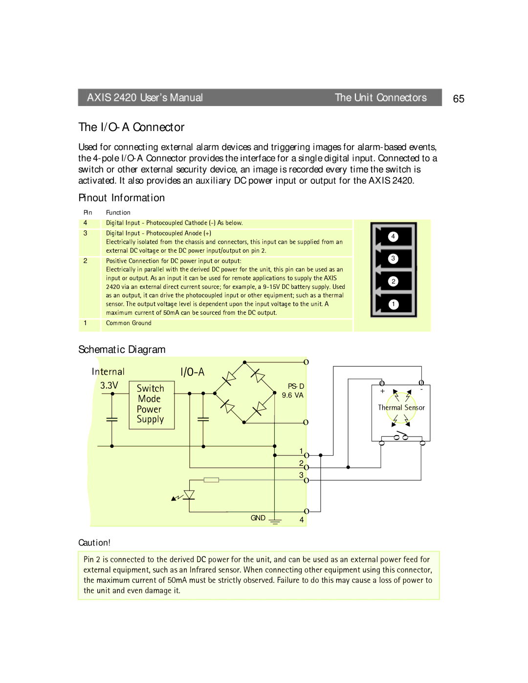
Pinout Information
Pin | Function |
4Digital Input - Photocoupled Cathode
3 | Digital Input - Photocoupled Anode (+) | 4 |
| Electrically isolated from the chassis and connectors, this input can be supplied from an | |
|
| |
| external DC voltage or the DC power input/output on pin 2. | 3 |
2 | Positive Connection for DC power input or output: | |
| Electrically in parallel with the derived DC power for the unit, this pin can be used as an |
|
| input or output. As an input it can be used for remote applications to supply the AXIS | 2 |
| 2420 via an external direct current source; for example, a | |
|
| |
| as an output, it can drive the photocoupled input or other equipment; such as a thermal |
|
| sensor. The output voltage level is dependent upon the input voltage to the unit. A | 1 |
| maximum current of 50mA can be sourced from the DC output. |
|
1Common Ground
Schematic Diagram
Internal |
| ! |
| o | |||
|
|
|
| ||||
3.3V | Switch |
| ! | ! | ! | ||
! | ! | 9.6 VA | |||||
Mode | |||||||
|
|
|
|
| |||
| Power |
|
|
|
|
| |
| Supply |
|
| ! |
| o | |
! |
|
| ! |
| ! | 1o | |
|
|
|
|
| ! | ||
|
|
|
|
|
| 2o | |
|
|
|
|
|
| 3o | |
|
|
|
| GND |
| o | |
|
|
|
|
| 4 | ||
o |
| o |
+ |
| - |
Thermal Sensor | ||
o | o | |
o | o | |
! |
|
|
! |
|
|
Caution!
Pin 2 is connected to the derived DC power for the unit, and can be used as an external power feed for external equipment, such as an Infrared sensor. When connecting other equipment using this connector, the maximum current of 50mA must be strictly observed. Failure to do this may cause a loss of power to the unit and even damage it.