FastIron GS Compact Layer 2 Switch Hardware Installation Guide
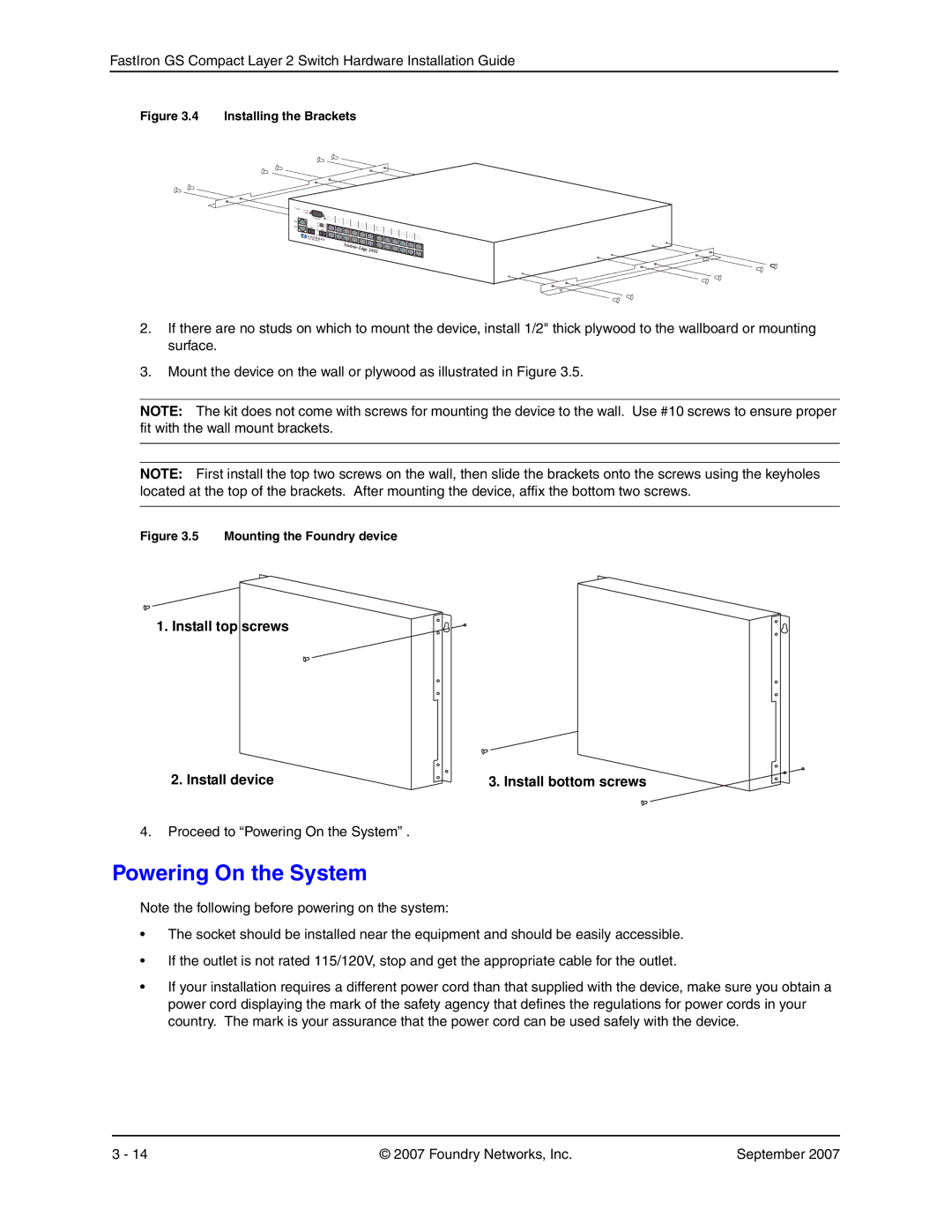
Figure 3.4 Installing the Brackets
Power | PS1 |
| PS2 |
25C |
|
26C |
|
| Console | 1 |
| 2 | |
| Lnk/ |
|
| Act | FDX |
| Lnk/ | |
25F | Act | FDX |
| Lnk | 26F |
| Act |
|
13![]() 14
14![]()
2.If there are no studs on which to mount the device, install 1/2" thick plywood to the wallboard or mounting surface.
3.Mount the device on the wall or plywood as illustrated in Figure 3.5.
NOTE: The kit does not come with screws for mounting the device to the wall. Use #10 screws to ensure proper fit with the wall mount brackets.
NOTE: First install the top two screws on the wall, then slide the brackets onto the screws using the keyholes located at the top of the brackets. After mounting the device, affix the bottom two screws.
Figure 3.5 Mounting the Foundry device
1. Install top screws
2. Install device | 3. Install bottom screws |
4.Proceed to “Powering On the System” .
Powering On the System
Note the following before powering on the system:
•The socket should be installed near the equipment and should be easily accessible.
•If the outlet is not rated 115/120V, stop and get the appropriate cable for the outlet.
•If your installation requires a different power cord than that supplied with the device, make sure you obtain a power cord displaying the mark of the safety agency that defines the regulations for power cords in your country. The mark is your assurance that the power cord can be used safely with the device.
3 - 14 | © 2007 Foundry Networks, Inc. | September 2007 |