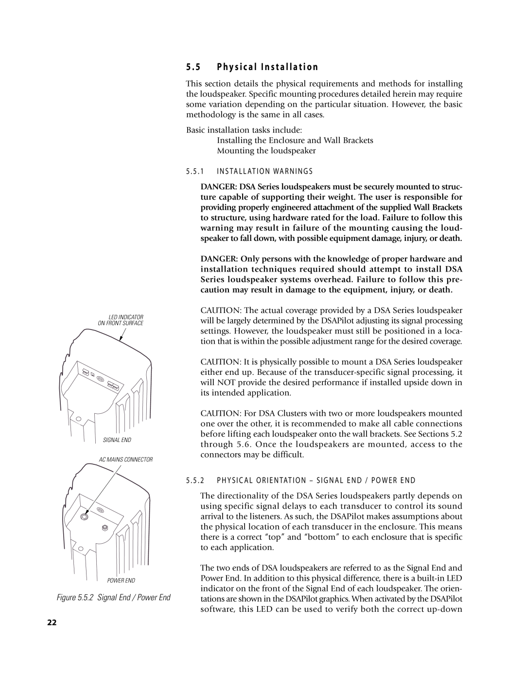
LED INDICATOR
ON FRONT SURFACE
SIGNAL END
AC MAINS CONNECTOR
POWER END
Figure 5.5.2 Signal End / Power End
5 . 5 | P h y s i c a l I n s t a l l a t i o n |
This section details the physical requirements and methods for installing the loudspeaker. Specific mounting procedures detailed herein may require some variation depending on the particular situation. However, the basic methodology is the same in all cases.
Basic installation tasks include:
Installing the Enclosure and Wall Brackets
Mounting the loudspeaker
5 . 5 . 1 I N S TA L L AT I O N WA R N I N G S
DANGER: DSA Series loudspeakers must be securely mounted to struc- ture capable of supporting their weight. The user is responsible for providing properly engineered attachment of the supplied Wall Brackets to structure, using hardware rated for the load. Failure to follow this warning may result in failure of the mounting causing the loud- speaker to fall down, with possible equipment damage, injury, or death.
DANGER: Only persons with the knowledge of proper hardware and installation techniques required should attempt to install DSA Series loudspeaker systems overhead. Failure to follow this pre- caution may result in damage to the equipment, injury, or death.
CAUTION: The actual coverage provided by a DSA Series loudspeaker will be largely determined by the DSAPilot adjusting its signal processing settings. However, the loudspeaker must still be positioned in a loca- tion that is within the possible adjustment range for the desired coverage.
CAUTION: It is physically possible to mount a DSA Series loudspeaker either end up. Because of the
CAUTION: For DSA Clusters with two or more loudspeakers mounted one over the other, it is recommended to make all cable connections before lifting each loudspeaker onto the wall brackets. See Sections 5.2 through 5.6. Once the loudspeakers are mounted, access to the connectors may be difficult.
5 . 5 . 2 P H Y S I C A L O R I E N TAT I O N – S I G N A L E N D / P O W E R E N D
The directionality of the DSA Series loudspeakers partly depends on using specific signal delays to each transducer to control its sound arrival to the listeners. As such, the DSAPilot makes assumptions about the physical location of each transducer in the enclosure. This means there is a correct “top” and “bottom” to each enclosure that is specific to each application.
The two ends of DSA loudspeakers are referred to as the Signal End and Power End. In addition to this physical difference, there is a
22