EAW D S A 2 3 0 5 . 2 . 4 C A B L I N G, 2.3 Basic CobraNet Diagram, 5.2.7MULTIPLE LOUDSPEAKERS

Models: D S A 2 3 0 D S A 2 5 0

1 44
Download 44 pages 19.35 Kb
Page 19
Image 19
5 . 2 . 4 C A B L I N G :

5 . 2 . 3 A D D I T I O N A L E Q U I P M E N T YO U M U S T S U P P LY F O R C O B R A N E T ™ :

·Loudspeaker interface:

EAW CM-1 CobraNet™ Interface Card (P/N 0005987) for each DSA Series loudspeaker

·Audio/Computer interface:

Converts signals to CobraNet™ protocol

·Ethernet switch or hub:

For networking multiple loudspeakers over Ethernet

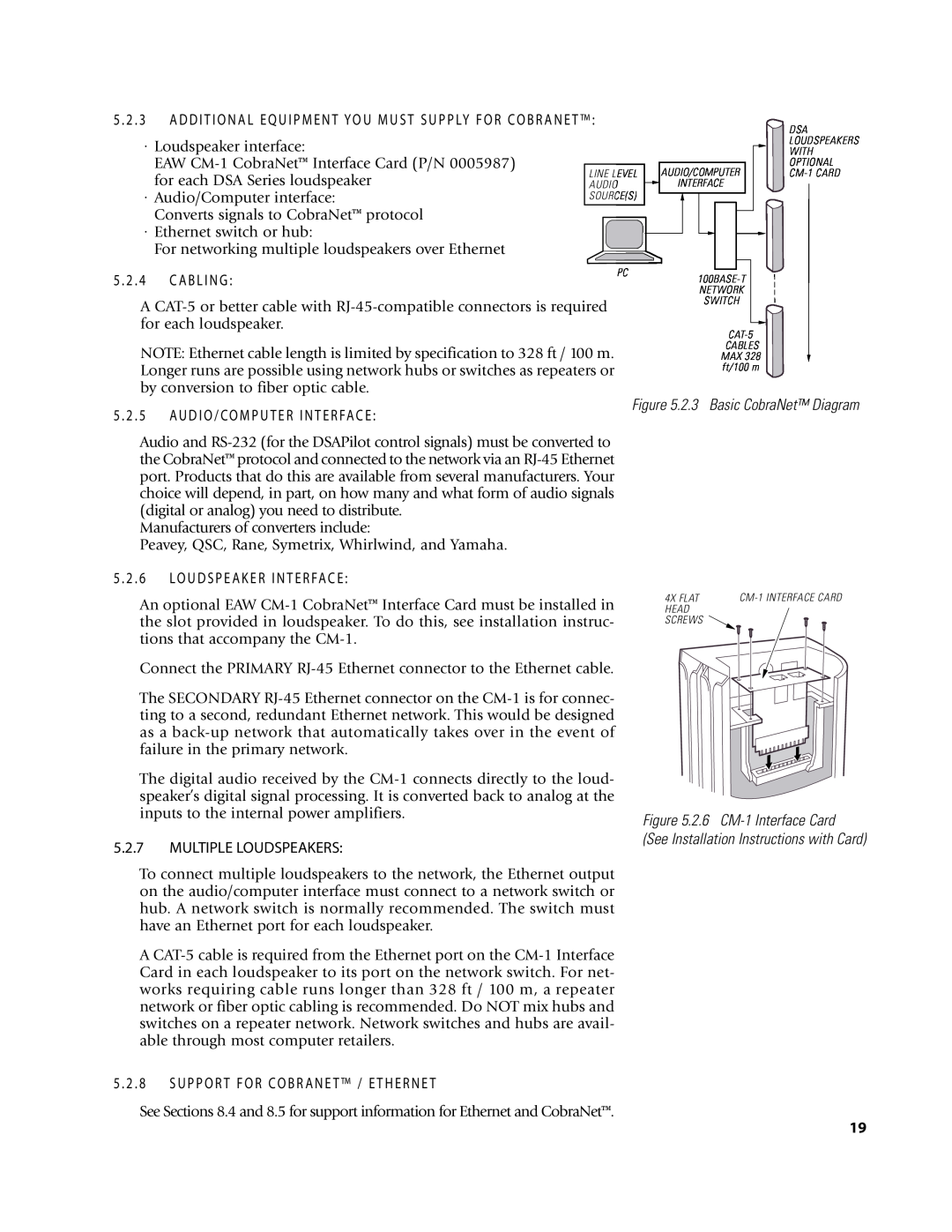
LINE LEVEL AUDIO SOURCE(S)

AUDIO/COMPUTER Figure 5.2.3 Basic CobraNet™ Diagram INTERFACE

DSA LOUDSPEAKERS WITH OPTIONAL

CM-1 CARD

5 . 2 . 4 C A B L I N G :

PC

100BASE-T NETWORK SWITCH

A CAT-5 or better cable with RJ-45-compatible connectors is required for each loudspeaker.

NOTE: Ethernet cable length is limited by specification to 328 ft / 100 m. Longer runs are possible using network hubs or switches as repeaters or by conversion to fiber optic cable.

CAT-5

CABLES MAX 328 ft/100 m

5 . 2 . 5 A U D I O / C O M P U T E R I N T E R FA C E :

Figure 5.2.3 Basic CobraNet™ Diagram

Audio and RS-232 (for the DSAPilot control signals) must be converted to the CobraNet™ protocol and connected to the network via an RJ-45 Ethernet port. Products that do this are available from several manufacturers. Your choice will depend, in part, on how many and what form of audio signals (digital or analog) you need to distribute.

Manufacturers of converters include:

Peavey, QSC, Rane, Symetrix, Whirlwind, and Yamaha.

5 . 2 . 6 LO U D S P E A K E R I N T E R FA C E :

An optional EAW CM-1 CobraNet™ Interface Card must be installed in the slot provided in loudspeaker. To do this, see installation instruc- tions that accompany the CM-1.

Connect the PRIMARY RJ-45 Ethernet connector to the Ethernet cable.

The SECONDARY RJ-45 Ethernet connector on the CM-1 is for connec- ting to a second, redundant Ethernet network. This would be designed as a back-up network that automatically takes over in the event of failure in the primary network.

The digital audio received by the CM-1 connects directly to the loud- speaker’s digital signal processing. It is converted back to analog at the inputs to the internal power amplifiers.

5.2.7MULTIPLE LOUDSPEAKERS:

To connect multiple loudspeakers to the network, the Ethernet output on the audio/computer interface must connect to a network switch or hub. A network switch is normally recommended. The switch must have an Ethernet port for each loudspeaker.

A CAT-5 cable is required from the Ethernet port on the CM-1 Interface Card in each loudspeaker to its port on the network switch. For net- works requiring cable runs longer than 328 ft / 100 m, a repeater network or fiber optic cabling is recommended. Do NOT mix hubs and switches on a repeater network. Network switches and hubs are avail- able through most computer retailers.

4X FLAT

CM-1 INTERFACE CARD

HEAD


SCREWS


Figure 5.2.6 CM-1 Interface Card

(See Installation Instructions with Card)

5 . 2 . 8 S U P P O R T F O R C O B R A N E T ™ / E T H E R N E T

See Sections 8.4 and 8.5 for support information for Ethernet and CobraNet™.

19

Page 19
Image 19
EAW D S A 2 3 0 5 . 2 . 4 C A B L I N G, 2.3 Basic CobraNet Diagram, 5 . 2 . 6 LO U D S P E A K E R I N T E R FA C E