2USB EZ-EXTENDER HARDWARE REFERENCE
This chapter describes the hardware design of the USB
•“System Architecture” on page
Describes the extension board’s configuration.
•“Processor Select Jumper (JP1)” on page
System Architecture
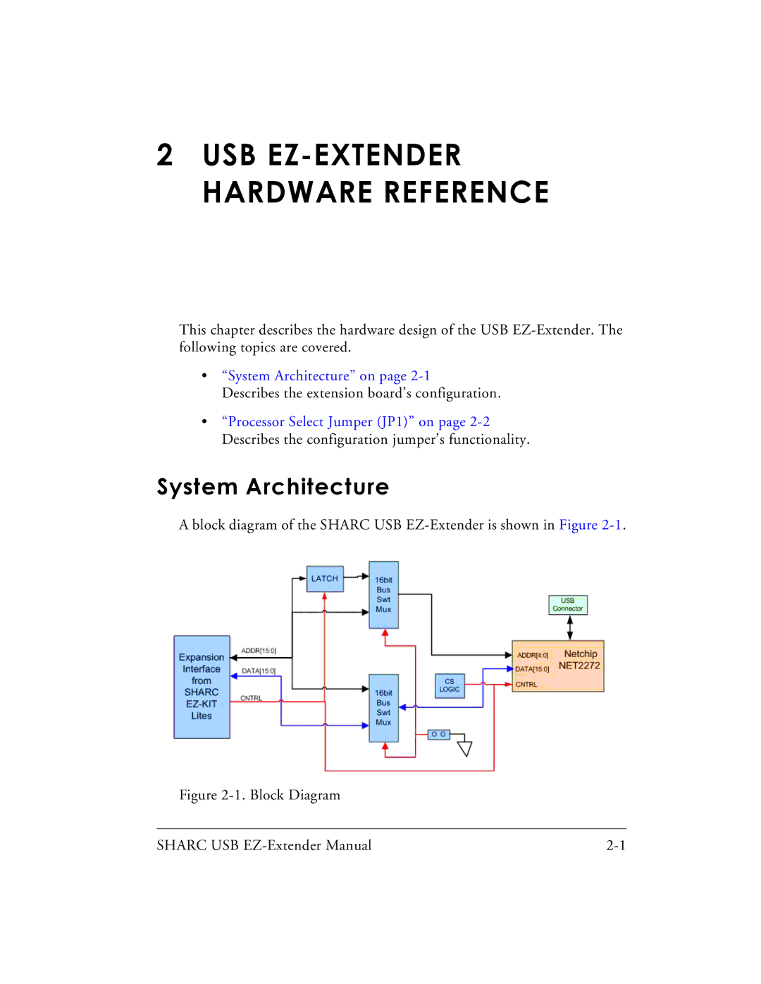
A block diagram of the SHARC USB
Figure 2-1. Block Diagram
SHARC USB |
