Analog Devices manual AD600/AD602, Applications, Time-GainControl TGC and Time-VariableGain TVG

Models: AD600 AD602

1 20
Download 20 pages 20.22 Kb
Page 8
Image 8
APPLICATIONS

AD600/AD602

APPLICATIONS

The full potential of any high performance amplifier can only be realized by careful attention to details in its applications. The following pages describe fully tested circuits in which many such details have already been considered. However, as is always true of high accuracy, high speed analog circuits, the schematic is only part of the story; this is no less true for the AD600 and AD602. Appropriate choices in the overall board layout and the type and placement of power supply decoupling components are very important. As explained previously, the input grounds A1LO and A2LO must use the shortest possible connections.

The following circuits show examples of time-gain control for ultrasound and for sonar, methods for increasing the output drive, and AGC amplifiers for audio and RF/IF signal process- ing using both peak and rms detectors. These circuits also illus- trate methods of cascading X-AMPs for either maintaining the optimal S/N ratio or maximizing the accuracy of the gain- control voltage for use in signal measurement. These AGC cir- cuits may be modified for use as voltage-controlled amplifiers for use in sonar and ultrasound applications by removing the detector and substituting a DAC or other voltage source for supplying the control voltage.

Time-Gain Control (TGC) and Time-Variable Gain (TVG)

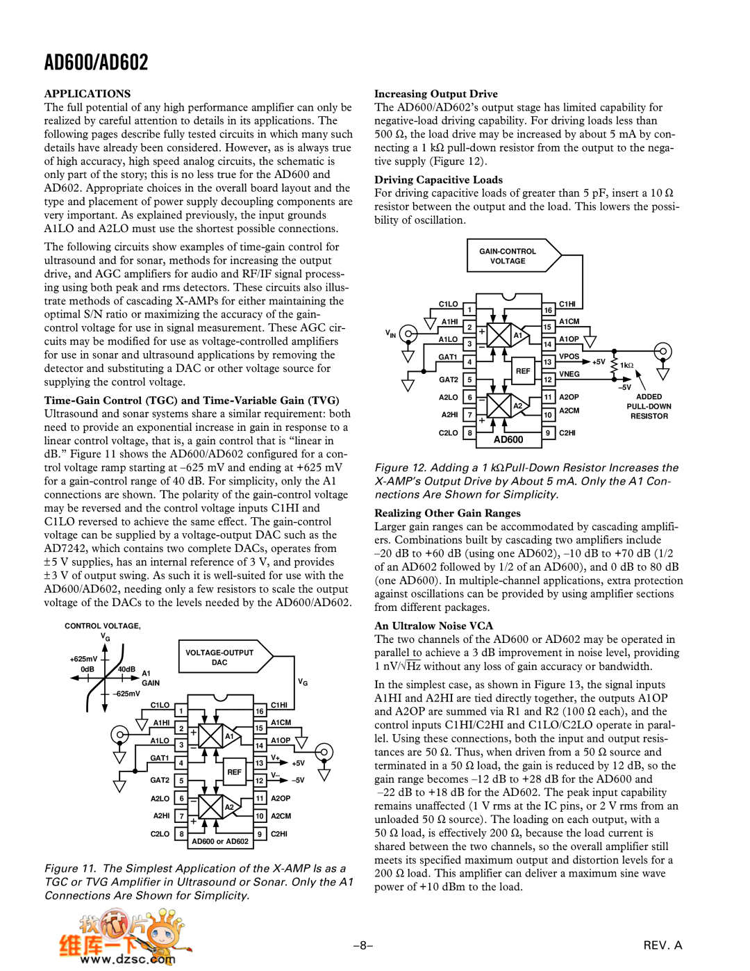
Ultrasound and sonar systems share a similar requirement: both need to provide an exponential increase in gain in response to a linear control voltage, that is, a gain control that is “linear in dB.” Figure 11 shows the AD600/AD602 configured for a con- trol voltage ramp starting at –625 mV and ending at +625 mV for a gain-control range of 40 dB. For simplicity, only the A1 connections are shown. The polarity of the gain-control voltage may be reversed and the control voltage inputs C1HI and C1LO reversed to achieve the same effect. The gain-control voltage can be supplied by a voltage-output DAC such as the AD7242, which contains two complete DACs, operates from

±5 V supplies, has an internal reference of 3 V, and provides

±3 V of output swing. As such it is well-suited for use with the AD600/AD602, needing only a few resistors to scale the output voltage of the DACs to the levels needed by the AD600/AD602.

CONTROL VOLTAGE,


VG


+625mV


VOLTAGE-OUTPUT


DAC


0dB

40dB A1


VG


GAIN


–625mV


C1LO

1

16

C1HI


A1HI

2

15

A1CM


A1LO

3

A1

A1OP


14


GAT1

4

13

V+


+5V


GAT2


REF

V–


5

12


–5V


A2LO

6

11

A2OP


A2HI


A2


7

10

A2CM


C2LO

8

9

C2HI


AD600 or AD602


Figure 11. The Simplest Application of the X-AMP Is as a TGC or TVG Amplifier in Ultrasound or Sonar. Only the A1 Connections Are Shown for Simplicity.

Increasing Output Drive

The AD600/AD602’s output stage has limited capability for negative-load driving capability. For driving loads less than

500 Ω, the load drive may be increased by about 5 mA by con- necting a 1 kΩ pull-down resistor from the output to the nega- tive supply (Figure 12).

Driving Capacitive Loads

For driving capacitive loads of greater than 5 pF, insert a 10 Ω resistor between the output and the load. This lowers the possi- bility of oscillation.


GAIN-CONTROL


VOLTAGE


C1LO

1

16

C1HI


A1HI

2

15

A1CM


VIN


A1LO

3

A1

A1OP


14


GAT1

4

13

VPOS

+5V

1kΩ


REF


VNEG


GAT2

5

12


–5V


A2LO

6

11

A2OP


ADDED


A2HI


A2

A2CM


PULL-DOWN


7

10


RESISTOR


C2LO

8

9

C2HI


AD600

Figure 12. Adding a 1 kΩPull-Down Resistor Increases the X-AMP’s Output Drive by About 5 mA. Only the A1 Con- nections Are Shown for Simplicity.

Realizing Other Gain Ranges

Larger gain ranges can be accommodated by cascading amplifi- ers. Combinations built by cascading two amplifiers include –20 dB to +60 dB (using one AD602), –10 dB to +70 dB (1/2 of an AD602 followed by 1/2 of an AD600), and 0 dB to 80 dB (one AD600). In multiple-channel applications, extra protection against oscillations can be provided by using amplifier sections from different packages.

An Ultralow Noise VCA

The two channels of the AD600 or AD602 may be operated in parallel to achieve a 3 dB improvement in noise level, providing 1 nV/√Hz without any loss of gain accuracy or bandwidth.

In the simplest case, as shown in Figure 13, the signal inputs A1HI and A2HI are tied directly together, the outputs A1OP and A2OP are summed via R1 and R2 (100 Ω each), and the control inputs C1HI/C2HI and C1LO/C2LO operate in paral- lel. Using these connections, both the input and output resis- tances are 50 Ω. Thus, when driven from a 50 Ω source and terminated in a 50 Ω load, the gain is reduced by 12 dB, so the gain range becomes –12 dB to +28 dB for the AD600 and –22 dB to +18 dB for the AD602. The peak input capability remains unaffected (1 V rms at the IC pins, or 2 V rms from an unloaded 50 Ω source). The loading on each output, with a 50 Ω load, is effectively 200 Ω, because the load current is shared between the two channels, so the overall amplifier still meets its specified maximum output and distortion levels for a 200 Ω load. This amplifier can deliver a maximum sine wave power of +10 dBm to the load.

–8–

REV. A

Page 8
Image 8
Analog Devices manual AD600/AD602, Applications, Time-GainControl TGC and Time-VariableGain TVG, Increasing Output Drive