|
|
|
|
|
|
|
|
|
| AD620 | |
|
|
| AD620A |
| AD620B |
| AD620S1 |
| |||
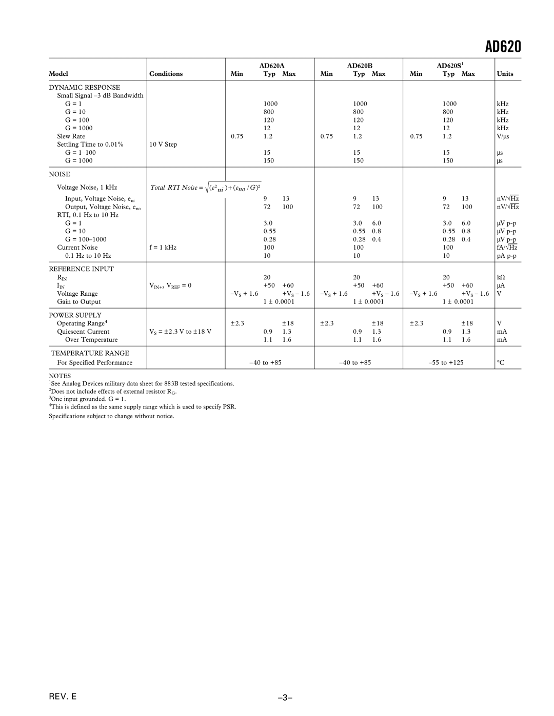
Model | Conditions | Min | Typ | Max | Min | Typ | Max | Min | Typ | Max | Units |
|
|
|
|
|
|
|
|
|
|
|
|
DYNAMIC RESPONSE |
|
|
|
|
|
|
|
|
|
|
|
Small Signal |
|
|
|
|
|
|
|
|
|
|
|
G = 1 |
|
| 1000 |
|
| 1000 |
|
| 1000 |
| kHz |
G = 10 |
|
| 800 |
|
| 800 |
|
| 800 |
| kHz |
G = 100 |
|
| 120 |
|
| 120 |
|
| 120 |
| kHz |
G = 1000 |
|
| 12 |
|
| 12 |
|
| 12 |
| kHz |
Slew Rate |
| 0.75 | 1.2 |
| 0.75 | 1.2 |
| 0.75 | 1.2 |
| V/μs |
Settling Time to 0.01% | 10 V Step |
|
|
|
|
|
|
|
|
| μs |
G = |
|
| 15 |
|
| 15 |
|
| 15 |
| |
G = 1000 |
|
| 150 |
|
| 150 |
|
| 150 |
| μs |
|
|
|
|
|
|
|
|
|
|
|
|
NOISE |
|
|
|
|
|
|
|
|
|
|
|
| = , 6 |
|
|
|
|
|
|
|
|
|
|
Voltage Noise, 1 kHz | - + , 3 |
|
|
|
|
|
|
|
| ||
Input, Voltage Noise, eni |
|
| 9 | 13 |
| 9 | 13 |
| 9 | 13 | nV/√Hz |
|
|
|
| ||||||||
Output, Voltage Noise, eno |
|
| 72 | 100 |
| 72 | 100 |
| 72 | 100 | nV/√Hz |
RTI, 0.1 Hz to 10 Hz |
|
|
|
|
|
|
|
|
|
| μV |
G = 1 |
|
| 3.0 |
|
| 3.0 | 6.0 |
| 3.0 | 6.0 | |
G = 10 |
|
| 0.55 |
|
| 0.55 | 0.8 |
| 0.55 | 0.8 | μV |
G = |
|
| 0.28 |
|
| 0.28 | 0.4 |
| 0.28 | 0.4 | μV |
Current Noise | f = 1 kHz |
| 100 |
|
| 100 |
|
| 100 |
| fA/√Hz |
0.1 Hz to 10 Hz |
|
| 10 |
|
| 10 |
|
| 10 |
| pA |
|
|
|
|
|
|
|
|
|
|
|
|
REFERENCE INPUT |
|
|
|
|
|
|
|
|
|
| kΩ |
RIN |
|
| 20 |
|
| 20 |
|
| 20 |
| |
IIN | VIN+, VREF = 0 |
| +50 | +60 |
| +50 | +60 |
| +50 | +60 | μA |
Voltage Range |
| +VS – 1.6 | +VS – 1.6 | +VS – 1.6 | V | ||||||
Gain to Output |
|
| 1 ± 0.0001 |
| 1 ± 0.0001 |
| 1 ± 0.0001 |
| |||
|
|
|
|
|
|
|
|
|
|
|
|
POWER SUPPLY |
| ± 2.3 |
| ± 18 | ± 2.3 |
| ± 18 | ± 2.3 |
| ± 18 |
|
Operating Range4 | VS = ± 2.3 V to ± 18 V |
|
|
| V | ||||||
Quiescent Current |
| 0.9 | 1.3 |
| 0.9 | 1.3 |
| 0.9 | 1.3 | mA | |
Over Temperature |
|
| 1.1 | 1.6 |
| 1.1 | 1.6 |
| 1.1 | 1.6 | mA |
|
|
|
|
|
|
|
|
|
|
|
|
TEMPERATURE RANGE |
|
|
|
|
|
|
|
|
|
|
|
For Specified Performance |
|
|
|
|
|
|
|
| °C | ||
|
|
|
|
|
|
|
|
|
|
|
|
NOTES
1See Analog Devices military data sheet for 883B tested specifications. 2Does not include effects of external resistor RG.
3One input grounded. G = 1.
4This is defined as the same supply range which is used to specify PSR.
Specifications subject to change without notice.
REV. E |
