DIP Switches and Jumpers
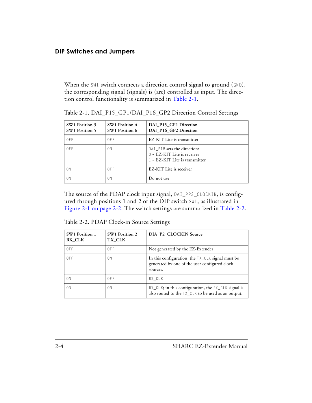
When the SW1 switch connects a direction control signal to ground (GND), the corresponding signal (signals) is (are) controlled as input. The direc- tion control functionality is summarized in Table
Table
SW1 Position 3 | SW1 Position 4 | DAI_P15_GP1 Direction | |
SW1 Position 5 | SW1 Position 6 | DAI_P16_GP2 Direction | |
|
|
| |
|
|
| |
OFF | OFF | ||
|
|
| |
OFF | ON | DAI_P18 sets the direction: | |
|
| 0 | = |
|
| 1 | = |
|
|
| |
ON | OFF | ||
|
|
| |
ON | ON | Do not use | |
|
|
|
|
The source of the PDAP clock input signal, DAI_PP2_CLOCKIN, is config- ured through positions 1 and 2 of the DIP switch SW1, as illustrated in Figure
Table
SW1 Position 1 | SW1 Position 2 | DIA_P2_CLOCKIN Source |
RX_CLK | TX_CLK |
|
|
|
|
|
|
|
OFF | OFF | Not generated by the |
|
|
|
OFF | ON | In this configuration, the TX_CLK signal must be |
|
| generated by one of the user configured clock |
|
| sources. |
|
|
|
ON | OFF | RX_CLK |
|
|
|
ON | ON | RX_CLK; in this configuration, the RX_CLK signal is |
|
| also routed to the TX_CLK to be used as an output. |
|
|
|
SHARC |