IF Up-Conversion (Option 7)
Option 7 adds an internal mixer that can be used for the generic
Mixer Type | Double Balanced |
RF, LO Range | 1 to 40 GHz |
|
|
IF Range | DC to 700 MHz |
Conversion Loss | 10 dB Typical |
|
|
Max Power into any Port | 30 dBm |
Isolation, RF to LO | 23 dB |
|
|
LO Drive Level (recommended) | +10 to +13 dBm |
Input P1dB | +3 dBm Typical |
The IF
User-Defined Modulation Waveform Software (Option 10)
An external software package provides the ability to download
23)memory. The MG3690A provides as standard with the LF Generator sinusoidal,
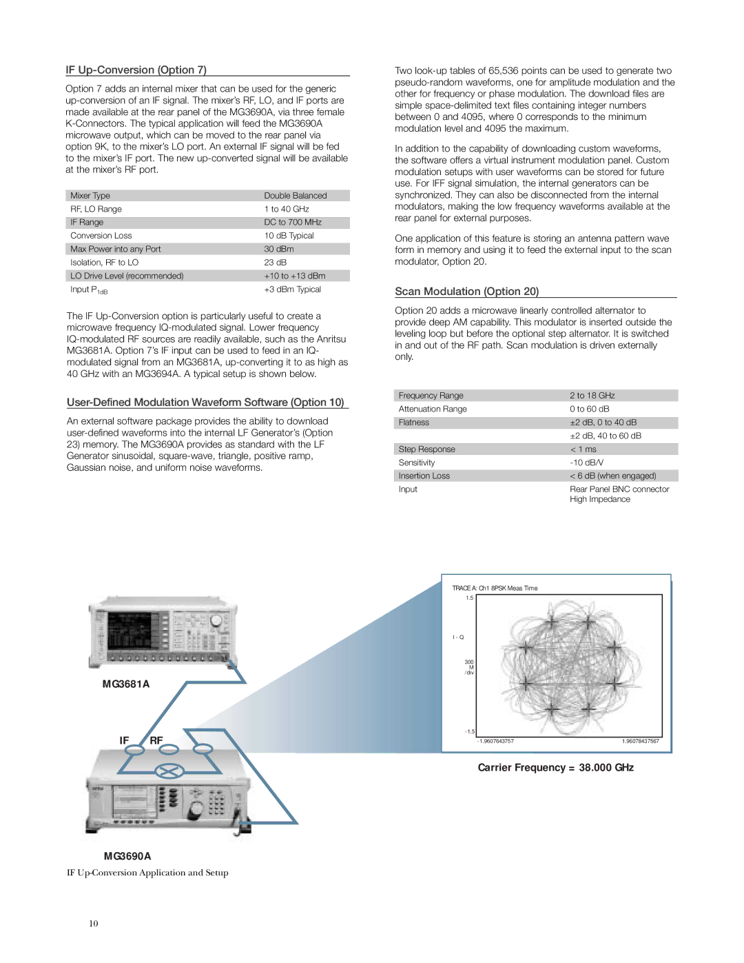
MG3681A
IF RF
MG3690A
IF
Two
In addition to the capability of downloading custom waveforms, the software offers a virtual instrument modulation panel. Custom modulation setups with user waveforms can be stored for future use. For IFF signal simulation, the internal generators can be synchronized. They can also be disconnected from the internal modulators, making the low frequency waveforms available at the rear panel for external purposes.
One application of this feature is storing an antenna pattern wave form in memory and using it to feed the external input to the scan modulator, Option 20.
Scan Modulation (Option 20)
Option 20 adds a microwave linearly controlled alternator to provide deep AM capability. This modulator is inserted outside the leveling loop but before the optional step alternator. It is switched in and out of the RF path. Scan modulation is driven externally only.
Frequency Range | 2 to 18 GHz |
Attenuation Range | 0 to 60 dB |
|
|
Flatness | ±2 dB, 0 to 40 dB |
| ±2 dB, 40 to 60 dB |
|
|
Step Response | < 1 ms |
Sensitivity | |
|
|
Insertion Loss | < 6 dB (when engaged) |
Input | Rear Panel BNC connector |
| High Impedance |
TRACE A: Ch1 8PSK Meas Time
1.5
I - Q
300 M /div
1.96078437567 |
Carrier Frequency = 38.000 GHz
10