EXT ALC IN
Provides for leveling the RF output signal externally with either a detector or power meter. Signal requirements are shown in the RF Output specifications.
RF OUTPUT
Provides for RF output from 50Ω source impedance. K Connector, female. Option 9 moves the RF Output connector to the rear panel.
10 MHz REF IN
Accepts an external 10 MHz ±100 Hz, 0 to +20 dBm
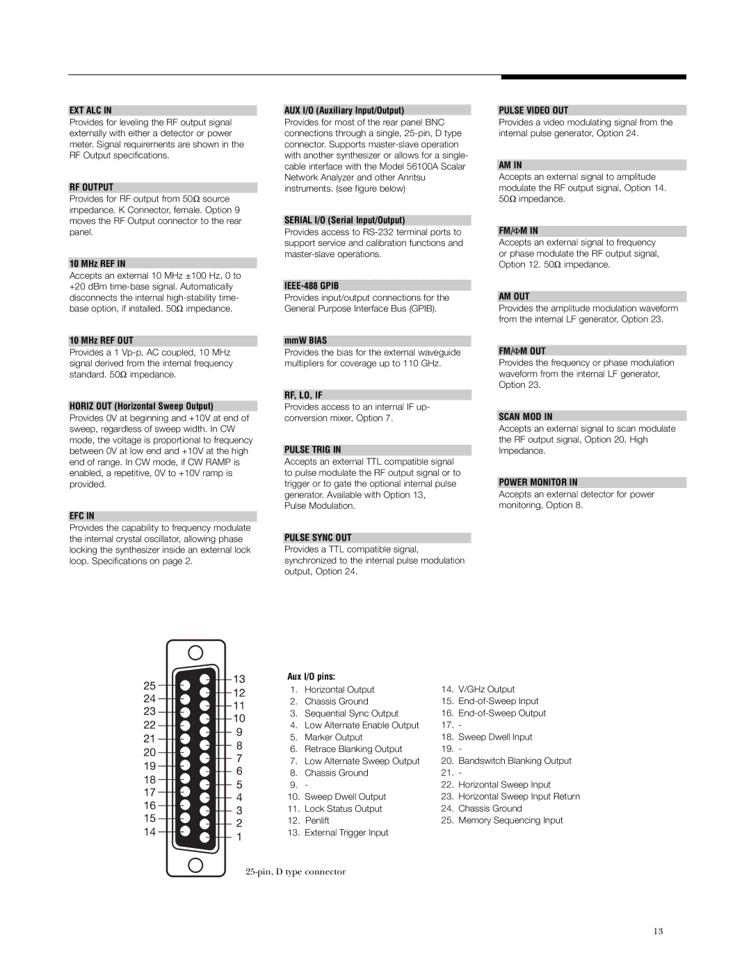
AUX I/O (Auxiliary Input/Output)
Provides for most of the rear panel BNC connections through a single,
SERIAL I/O (Serial Input/Output)
Provides access to
IEEE-488 GPIB
PULSE VIDEO OUT
Provides a video modulating signal from the internal pulse generator, Option 24.
AM IN
Accepts an external signal to amplitude modulate the RF output signal, Option 14. 50Ω impedance.
FM/Φ M IN
Accepts an external signal to frequency or phase modulate the RF output signal, Option 12. 50Ω impedance.
disconnects the internal
10 MHz REF OUT
Provides a 1
HORIZ OUT (Horizontal Sweep Output)
Provides 0V at beginning and +10V at end of sweep, regardless of sweep width. In CW mode, the voltage is proportional to frequency between 0V at low end and +10V at the high end of range. In CW mode, if CW RAMP is enabled, a repetitive, 0V to +10V ramp is provided.
EFC IN
Provides the capability to frequency modulate the internal crystal oscillator, allowing phase locking the synthesizer inside an external lock loop. Specifications on page 2.
Provides input/output connections for the General Purpose Interface Bus (GPIB).
mmW BIAS
Provides the bias for the external waveguide multipliers for coverage up to 110 GHz.
RF, LO, IF
Provides access to an internal IF up- conversion mixer, Option 7.
PULSE TRIG IN
Accepts an external TTL compatible signal to pulse modulate the RF output signal or to trigger or to gate the optional internal pulse generator. Available with Option 13,
Pulse Modulation.
PULSE SYNC OUT
Provides a TTL compatible signal, synchronized to the internal pulse modulation output, Option 24.
Aux I/O pins:
AM OUT
Provides the amplitude modulation waveform from the internal LF generator, Option 23.
FM/Φ M OUT
Provides the frequency or phase modulation waveform from the internal LF generator, Option 23.
SCAN MOD IN
Accepts an external signal to scan modulate the RF output signal, Option 20. High Impedance.
POWER MONITOR IN
Accepts an external detector for power monitoring, Option 8.
1. | Horizontal Output | 14. | V/GHz Output |
2. | Chassis Ground | 15. | |
3. | Sequential Sync Output | 16. | |
4. | Low Alternate Enable Output | 17. | - |
5. | Marker Output | 18. | Sweep Dwell Input |
6. | Retrace Blanking Output | 19. | - |
7. | Low Alternate Sweep Output | 20. | Bandswitch Blanking Output |
8. | Chassis Ground | 21. | - |
9. | - | 22. | Horizontal Sweep Input |
10. | Sweep Dwell Output | 23. | Horizontal Sweep Input Return |
11. | Lock Status Output | 24. | Chassis Ground |
12. | Penlift | 25. | Memory Sequencing Input |
13. | External Trigger Input |
|
|
13