3.Line up your motherboard with the standoff holes, and remember which holes are lined up. Not all motherboards will match with all the provided holes; this is normal, and won't affect functionally. (In other words, there will likely be extra holes.)

4.Remove your motherboard by lifting it up.

5.Screw the brass standoffs into the threaded holes that line up with your motherboard. Do not overtighten the standoffs. Some standoffs may be pre-installed for your convenience.

6.Place your motherboard on the brass standoffs.

7.Screw in your motherboard to the standoffs with the provided Philips-head screws. Your motherboard is now installed.

CONNECTING THE POWER AND LED

The power supply conforms to the latest ATX12V Version 2.0 standard. It is also backwards-compatible with previous ATX form factor power supplies. Before you connect the power supply to any of your devices, please consult the appropriate user manuals for your motherboard and other peripherals.

The power supply is also equipped with a 3-pin fan signal connector. Connect it to one of the fan connectors on your motherboard. You may monitor the speed of the rear power supply fan through your motherboard BIOS or through the monitoring software that's supplied with your motherboard. Note: At low temperatures, the fan may run as slow as 950RPM. At these speeds, some motherboards may not properly detect the fan speed and may generate false warnings of fan failure. To ensure proper monitoring of the fan, please check your motherboard manual.

1.

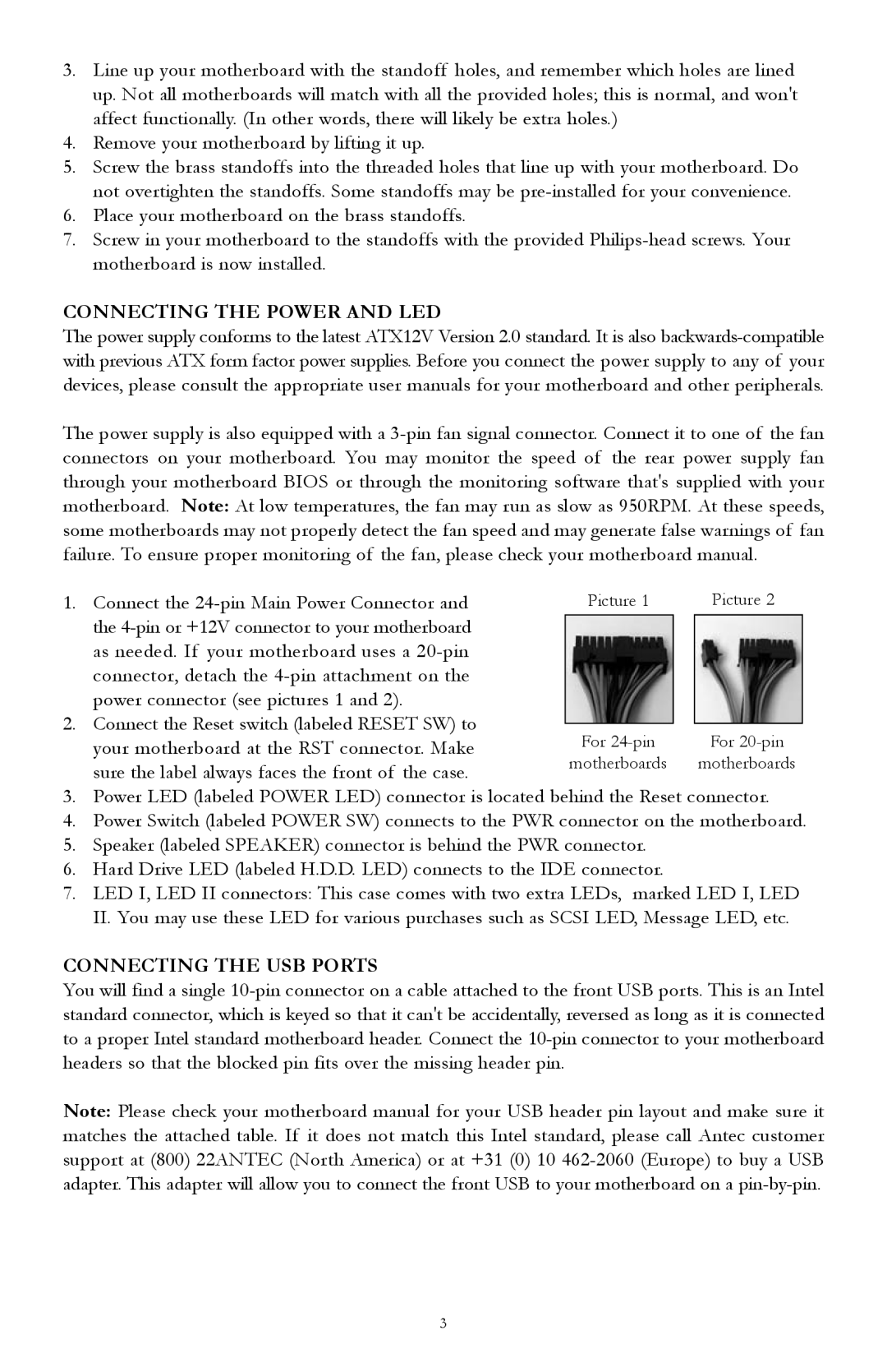
Connect the 24-pin Main Power Connector and

Picture 1


Picture 2


the 4-pin or +12V connector to your motherboard


as needed. If your motherboard uses a 20-pin


connector, detach the 4-pin attachment on the


power connector (see pictures 1 and 2).


2.

Connect the Reset switch (labeled RESET SW) to


For 24-pin


For 20-pin


your motherboard at the RST connector. Make


sure the label always faces the front of the case.

motherboards


motherboards


3.Power LED (labeled POWER LED) connector is located behind the Reset connector.

4.Power Switch (labeled POWER SW) connects to the PWR connector on the motherboard.

5.Speaker (labeled SPEAKER) connector is behind the PWR connector.

6.Hard Drive LED (labeled H.D.D. LED) connects to the IDE connector.

7.LED I, LED II connectors: This case comes with two extra LEDs, marked LED I, LED II. You may use these LED for various purchases such as SCSI LED, Message LED, etc.

CONNECTING THE USB PORTS

You will find a single 10-pin connector on a cable attached to the front USB ports. This is an Intel standard connector, which is keyed so that it can't be accidentally, reversed as long as it is connected to a proper Intel standard motherboard header. Connect the 10-pin connector to your motherboard headers so that the blocked pin fits over the missing header pin.

Note: Please check your motherboard manual for your USB header pin layout and make sure it matches the attached table. If it does not match this Intel standard, please call Antec customer support at (800) 22ANTEC (North America) or at +31 (0) 10 462-2060 (Europe) to buy a USB adapter. This adapter will allow you to connect the front USB to your motherboard on a pin-by-pin.

3

Page 3
Image 3
Antec 1088AMG, TX1050B user manual Connecting the Power and LED, Connecting the USB Ports

1088AMG, TX1050B specifications

The Antec 1088AMG and TX1050B are two prominent computer cases that cater to the needs of gamers and PC enthusiasts, offering a blend of functionality, aesthetics, and expandability. Both models stand out in the crowded market of PC enclosures, showcasing their unique features and technologies.

Starting with the Antec 1088AMG, this mid-tower case is designed with an emphasis on cooling and airflow. It boasts a sleek black finish, complemented by a sturdy steel construction that ensures durability. The case features a spacious interior, allowing for easy installation of high-end components and ample room for cable management. Its front panel includes two USB 2.0 ports, audio inputs, and a power/reset button, providing convenient access for users.

The cooling capabilities of the 1088AMG are noteworthy, with support for multiple fans. The case comes pre-equipped with two120mm fans, one at the front and one at the rear, promoting efficient airflow. Additionally, the case supports extra fan placements, which can be crucial in keeping high-performance components, such as powerful graphics cards and CPUs, from overheating during intensive tasks.

Transitioning to the TX1050B, this model emphasizes versatility and expandability. It features a classic design with a glossy black front panel and a perforated metal side panel for enhanced ventilation. Similar to the 1088AMG, the TX1050B is designed for optimal airflow with support for several cooling options. It can accommodate up to five fans, ensuring that the interior remains cool even under heavy loads.

The TX1050B also understands the importance of space and organization. It includes seven expansion slots, enabling users to install multiple graphics cards or other expansion cards. The case has dedicated cable management features, allowing for tidy wiring and enhanced airflow. Additionally, the tool-less drive bays simplify the installation of hard drives and optical drives, making the building process straightforward.

Both the Antec 1088AMG and TX1050B support a wide range of Motherboards, from Micro-ATX to ATX, making them flexible choices for various build configurations. The cases also include dust filters to keep the interior clean and maintain performance.

In conclusion, the Antec 1088AMG and TX1050B provide solid performance, excellent thermal solutions, and user-friendly features. Their designs cater to those who demand reliability and expandability from their computer cases, ensuring they can build robust systems that can handle demanding applications. Whether for gaming or general use, these cases offer a comprehensive package for any PC builder.