1088AMG, TX1050B specifications
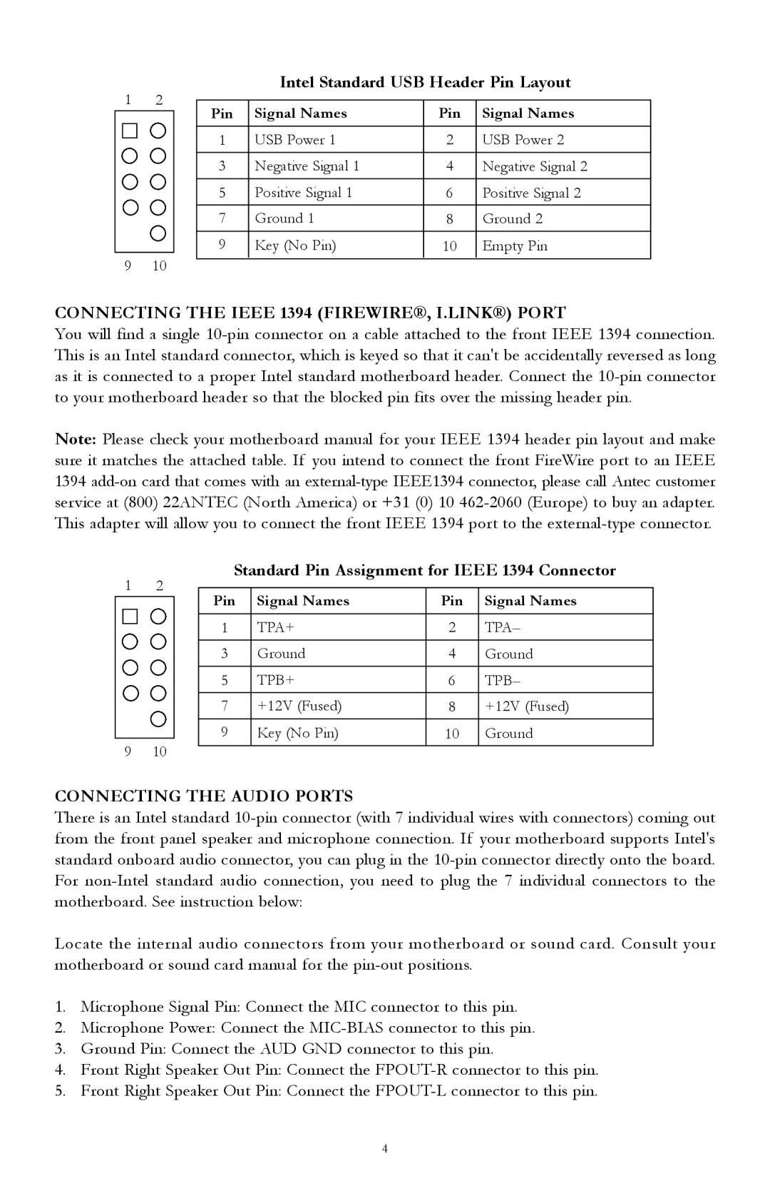
The Antec 1088AMG and TX1050B are two prominent computer cases that cater to the needs of gamers and PC enthusiasts, offering a blend of functionality, aesthetics, and expandability. Both models stand out in the crowded market of PC enclosures, showcasing their unique features and technologies.Starting with the Antec 1088AMG, this mid-tower case is designed with an emphasis on cooling and airflow. It boasts a sleek black finish, complemented by a sturdy steel construction that ensures durability. The case features a spacious interior, allowing for easy installation of high-end components and ample room for cable management. Its front panel includes two USB 2.0 ports, audio inputs, and a power/reset button, providing convenient access for users.
The cooling capabilities of the 1088AMG are noteworthy, with support for multiple fans. The case comes pre-equipped with two120mm fans, one at the front and one at the rear, promoting efficient airflow. Additionally, the case supports extra fan placements, which can be crucial in keeping high-performance components, such as powerful graphics cards and CPUs, from overheating during intensive tasks.
Transitioning to the TX1050B, this model emphasizes versatility and expandability. It features a classic design with a glossy black front panel and a perforated metal side panel for enhanced ventilation. Similar to the 1088AMG, the TX1050B is designed for optimal airflow with support for several cooling options. It can accommodate up to five fans, ensuring that the interior remains cool even under heavy loads.
The TX1050B also understands the importance of space and organization. It includes seven expansion slots, enabling users to install multiple graphics cards or other expansion cards. The case has dedicated cable management features, allowing for tidy wiring and enhanced airflow. Additionally, the tool-less drive bays simplify the installation of hard drives and optical drives, making the building process straightforward.
Both the Antec 1088AMG and TX1050B support a wide range of Motherboards, from Micro-ATX to ATX, making them flexible choices for various build configurations. The cases also include dust filters to keep the interior clean and maintain performance.
In conclusion, the Antec 1088AMG and TX1050B provide solid performance, excellent thermal solutions, and user-friendly features. Their designs cater to those who demand reliability and expandability from their computer cases, ensuring they can build robust systems that can handle demanding applications. Whether for gaming or general use, these cases offer a comprehensive package for any PC builder.
