Chapter 4 Adjustments and settings for recording
AUDIO CH1:
The function for switching the channel 1 input signal is allocated. Each press advances the setting through the sequence FRONT > W.L.> REAR. Note that it is also possible to change the setting by operating the AUDIO IN switch. Whichever control is operated last takes precedence.
AUDIO CH2:
The function for switching the channel 2 input signal is allocated. Each press advances the setting through the sequence FRONT > W.L.> REAR. Note that it is also possible to change the setting by operating the AUDIO IN switch. Whichever control is operated last takes precedence.
REC SW:
The function of the VTR’s START button is allocated.
Y GET:
The function for displaying the brightness level of the center marker area is allocated.
RET SW:
The function of the RET button on the lens is allocated.
D.ZOOM:
This magnifies the picture angle
<Note>
The LINE MIX and D.ZOOM functions do not work concurrently. The function which is enabled last takes precedence, and the function set before it is canceled.
4-8-5 Setting the color temperature manually
The white balance can be adjusted manually using the color temperature settings. These manual color temperature settings can be performed for the PRST, A and B settings of the WHITE BAL switch.
Perform menu operations to open the <WHITE BALANCE MODE> screen from the OPERATION page, and select VAR as the setting for the AWB A item and AWB B item. The manual color temperature adjustment function is now valid.
The color temperatures are set using the COLOR TEMP PRE item, COLOR TEMP A item and COLOR TEMP B item.
#< WHITE BALANCE MODE >
FILTER INH | :ON |
SHOCKLESS AWB | :NORMAL |
AWB AREA | :25% |
AWB&ABB OFFSET | :OFF |
COLOR TEMP PRE | :3200K |
AWB A | :MEM |
COLOR TEMP A | :3200K |
AWB B | :MEM |
COLOR TEMP B | :3200K |
4-9 Data handling
Setup card
Use of the setup memory card (optional accessory) enables the setting menu contents to be saved. Use of this data speeds up the process of reproducing suitable setup statuses.
≥Multimedia cards or SD memory cards can be used as the setup cards.
| 4 |
The setup card can be inserted or removed before or after the power is switched on.
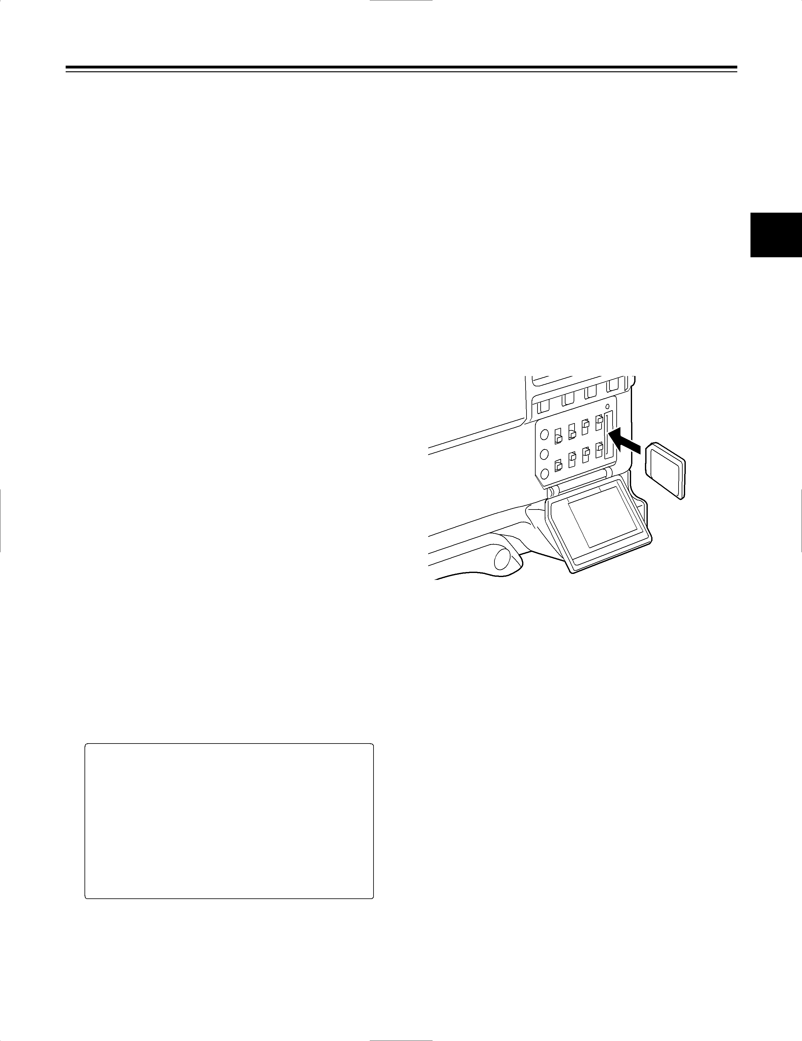
Inserting the setup card
Open the switch cover, position the setup card (optional accessory) with its cutout facing up, insert it into the setup card insertion slot, and close the switch cover.
<Note>
Before inserting the setup card, check that it is pointed in the correct direction. If the card meets with resistance and if it is difficult to insert, it may mean that it is the wrong way round or upside down. Do not force the card into the slot but check its direction again and insert it properly.
Removing the setup card
Open the switch cover, check that the BUSY lamp is not lighted, and push the setup card further into the unit. This causes the card to partially pop out from the insertion slot. Take hold of the card, remove it, and close the switch cover.
Bear in mind the following points when using and saving the setup cards.
≥Avoid high temperatures and high humidity levels.
≥Keep the cards away from water.
≥Avoid exposing the cards to electrical charges.
Keep the setup card inside the unit with the cover closed.
49